►
From YouTube: IETF109-RTGWG-20201117-0500
Description
RTGWG meeting session at IETF109
2020/11/17 0500
https://datatracker.ietf.org/meeting/109/proceedings/
A
A
A
A
A
Next,
please
so
no
rex
is
published
since
last
atf
next
slide,
so
we've
got
two
drafts
that
are
expected.
So
bgp
peak
is
the
draft
I
mentioned
before
is
still
waiting
for
ipl
ipr
responses,
so
I
clearly
remember
cisco
patented
it
10
years
ago,
or
so
I
also
mailed
clarence
and
us
for
clarification.
So
hopefully
we
should
be
able
to
solve
this
soon
and
actually
go
through
working
group
called
another
document.
Is
young
crib
extended
from
my
point
of
view
very
ready,
for
let's
also
expect,
let's
go
walking
group
last
coulson
next
slide.
Please.
A
A
So
there
are
a
number
of
ongoing
documents.
The
kfa
has
been
updated
day
before
yesterday.
So
thanks
for
updating,
it
looks
really
good.
Atnbgp
has
a
bunch
of
very
interesting
discussions.
I'm
going
rpm
model
and
qs
models
are
getting
very
close
to
being
ready
for
working
with
plus
calls
from
a
perspective
as
well.
A
B
C
A
D
What
will
be
the
outcome,
and
that
is
a
major
problem
because
it
it
grows,
but,
as
somebody
said,
it
also
kills
unnecessary.
Kills
human
brain
cells
wasting
their
time
over
something
trying
to
figure
out
if
it
should
be
there
or
not
in
for
a
variety
of
reasons,
the
configs
are
growing
and
they're,
not
getting
optimized.
D
Please
so,
where
do
we
see
that
the
multi-level
configs
could
help?
One
of
them
is
service
assurance
and
network
slicing.
We
will
talk
a
little
bit
more
about
those
two
examples,
a
little
bit
in
in
the
next
slides,
but
also
in
network
migrations
and
the
merging
of
of
the
configurations
and
server
levels
as
well
in
zero
touch
provisioning
so
with
the.
D
If,
if
we
have
a
large
service
instances
that
we
are
looking
to
add
to
the
network,
if
we
are
trying
to
do
that
in
one
large
file,
it's
a
question
where
all
those
things
have
to
be
added
correctly
by
being
able
to
split
it
up
in
multiple
levels.
We
believe
that
this
can
be
simplified
and
it
can
be
done
in
several
smaller
steps,
making
sure
that
the
correct
configuration
is
being
done,
but
in
case
also
something
is
wrong.
It
should
be
easy
to
remove
one
of
those
levels
and
pretty
much.
D
D
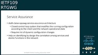
So
the
the
service
assurance
is
a
is
a
very
interesting
example.
The
draft
benos
draft
for
the
service
assurance
architecture
is
essentially
a
closed
control.
Loop
system
that
modifies
the
running,
configuration
and
verifies
that
the
intent
and
the
configurational
and
the
network
operational
state
are
in
thing
and
there
the
idea
there
is
that
you
can
verify
also
the
slas,
and
this
requires
a
lot
of
active
and
active
changing
of
the
network
configuration
now
as
if
this
would
be
done
in
the
older
ways
trying
to
manage
all
those
config
changes
is
a
complex
task.
D
D
The
other
area
is
with
the
network
slice
again
as
besides
in
network
slicing,
we
have
to.
We
can
view
it
from
two
perspective.
We
can
view
slices
as
address
slices,
but
we
also
can
view
it
as
separate
management
slices
where
the
management
slice
could
be
sorry
that
the
the
network,
slice
with
management
isolation
could
be
created
by
using
logical
elements
on
a
network
device,
and
the
issue
there
as
well
is
how
make
sure
that
the
in
case
there
is
no
phone
management
separation
on
the
device.
D
How
can
be
created
a
separation
of
the
component,
each
slice
configuration
that
those
will
not
be
conflicting,
which
other
the
slicing
brings
two
dimensions.
One
of
them
is
the
now
this
actually,
let
me
finish
and
then
go
to
the
next
slide,
so
the
as
the
slicing
configuration
can
be
hierarchical
and
recursive.
D
D
D
D
D
Instance
next
slide,
please.
So
I
said
we
are
presenting
this
to
the
here
in
the
routing
working
group,
but
also
in
the
nmrg.
This
is
just
a
start
and
we
are
looking
to
collect
feedback
and
problems
that
the
community
might
see
with
with
our
proposal
summit.
If
you
have
some
additions
as
well
with
the
idea
that
we
have
for
a
potential
solution.
A
D
So
that
is,
that
is
one
of
the
problems
that
we
are
looking
into.
It
said
we
are
starting
to
look
into
it
because
it's
a
growing
problem,
but
I
don't
have
a
good
answer
for
that.
Now,
it's
a
good
one
to
write
down-
and
I
know
zhu
fang-
did
a
little
bit
of
look
looking
into
that.
But
this
is
the
area
that
requires
much
more
work.
It's
it
said
it's
the
beginning
of.
A
A
A
F
F
Okay,
thank
you.
This
page
shows
the
overview
of
midpoint
protection
mechanisms.
Actually,
our
proposal
is
quite
straightforward.
If
an
endpoint
indicated
by
the
second
link
the
year
loose
sr-60
pass,
there
are
three
steps
during
the
convergence,
as
the
slide
shows
in
the
first
step,
the
igp
is
not
converged
yet
larger.
The
adjacency
of
the
field
endpoint
will
perform
as
a
repair.
Node
in
this
picture
is
the
node
b
and
send
the
packet
to
the
next
endpoint
in
the
segment.
F
In
the
second
step,
igp
has
already
converged
in
some
upstream
nodes
of
the
field.
Endpoint,
maybe
b
or
maybe
a
in
the
picture.
There
is
no
a
routine
to
e
in
the
fib
of
these
nodes,
so
these
upstream
nodes
will
be
the
repair
node
and
perform
the
proxy
forwarding
action
again.
Send
the
packet
to
the
next
endpoint
in
the
segment
in
the
third
part.
F
F
This
is
a
brief
history
of
this
document
in
version
0
and
version
one.
We
mainly
focus
on
the
mechanisms,
definition
and
inversion,
two
actually
based
on
the
discussion
about
security
in
the
itf
community.
We
also
end
the
section
to
provide
security
consideration
section
six.
Basically,
we
limit
the
the
proxy
forwarding
behavior
in
srv6
domain
and
the
inversion
3,
which
is
the
latest
version
based
on
the
discussion,
is
three
minute
list.
F
F
F
F
G
F
F
Oh
yes,
actually,
this
is
described
in
the
the
three
stage.
Maybe
we
can
go
back
to
the
slide
two.
I
think
there
are
three
stage
when
the
igp
is
converged
and
the
when
the
when
the
igp
has
already
converged.
We
cannot
find
the
routine
to
e
anymore,
so
we
just
some
upstream
nodes
will
do
the
proxy
forwarding
and
if
the
there
is
no
igp
convergence,
yet
the
the
node
b,
the
adjacency
of
the
failed
node,
will
know
that
something
wrong
has
happened,
so
he
will
do
the
proxy
forwarding.
G
F
G
G
F
F
Yes,
actually,
the
the
e
note
it
can
be,
for
example,
just
an
endpoint,
maybe
n
dot
x,
or
maybe
it's
just
can
just
some
other
functions.
But
if
the
node
b
do
the
proxy
for
wording,
it
just
can
do
the
function
about
forwarding
the
packet
directly
to
the
destination.
If
there
is
other
functions
should
be.
F
I
F
There
are
some
cases
have
been
this
discussed
in
the
document
different
types
of
b.
Maybe
it
is
just
a
transient
node
or
maybe
it
is
another
endpoint
in
the
second
list.
So
we
we
in
the
different
classes
of
node
b.
We
have
some
different
cases
and
discussed
in
different
sections
in
document,
but
for
different
types
of
node
e
for
node
b.
If
it
will
do
the
proxy
for
wording,
it
just
can't
do
something
like
and
maybe
just
find,
the
next
segment
and
forward
packman
packet
to
node
d.
In
this
case.
F
A
J
Stewart,
so
I'm
afraid
my
question
was
very
similar
when
you
set
up
segment
routing
path.
You
set
that
path
up
for
a
reason,
and
that
reason
may
be
that
you
want
traffic
to
go
to
a
particular
node
for
a
particular
reason,
or
you
want
to
protect
other
paths
from
being
overloaded
by
that
traffic.
So,
with
all
repairs
and
alternates,
I
get
really
worried
that
you're
going
to
bust
all
the
original
reasons
for
creating
the
sr
path,
and
I
would
imagine
the
only
node
that
could
actually
re-route
a
path.
J
F
F
F
J
A
A
K
K
I
just
saw
you
that,
regarding
the
comments
I
mean
the
first
one,
the
the
other
function
on
the
knee
to
be
exactly
executed
from
up
on
the
wheel.
That's
the
different
function,
adjuster
for
the
for
the
projection
and
the
other
x.
I
mean
that's
a
different
scenario.
The
second
one
I
mean
the
the
confused.
K
The
confusion
always
happens
between
the
between
the
this
me,
the
protection
and
the
under
the
trfa.
From
my
point
of
view,
I
mean
that's
because
the
this
is
the
sr
traffic
engineering
scenario,
because
that's
the
segment
list
that
will
go
through
the
e
node.
So
that's
when
the
e-node
is
a
field,
so
you
need
some.
This
is
the
special
process
in
the
b
node,
that's
the
proxy
file
for
wording,
because
they
need
to
reduce
some
of
this,
the
sl
or,
and
also
the
move,
the
pointer
back
this
way.
K
A
Yeah
so
I
reading
the
draft
motivation
is
unclear.
I
mean
I,
I
can
kind
of
understand
what
you're
trying
to
achieve,
but
it's
not
clear
really
without
proper
understanding,
so
draft,
definitely
not
ready
for
working
group
adoption
and
please
please,
maybe
ask
someone
else
to
read
it
and
tell
you
what's
unclear
because
yeah,
it's
very
difficult
to
understand
what
you're
trying
to
achieve,
and
I
have
a
question
about
experimental
track
on
it.
I
mean
you,
don't
define
any
new
extensions,
you're
kind
of
defying
possible
behavior,
so
probably
informational
would
be
better
trackers
than
experimental.
F
I
There
are
multiple
documents
related
to
terminated,
an
srt
bus
or
a
tunnel
on
the
wing
coordination
because
they
are
related
to
the
reddit
subject.
The
mentorship
is
a
so
it's
not
about
fast
reward,
you're
terminating
a
tunnel.
So
what
do
you
do,
whether
it's
a
vpn,
whether
it's
a
srt
asked
mother
except
service
function?
A
F
M
H
H
H
H
So
another
alternate
for
this
could
be
do
this
from
ingress,
which
is
the
bgp
pickage.
But
this
is
an
alternate
solution
to
that,
where
you
protect
the
traffic
on
the
egress
itself
so
and
you
can
provide
faster
protection
with
the
egress
protection
mechanisms
like
you,
can
do
a
50
millisecond
conversions
in
this
case.
H
H
So,
let's
see
how
this
solution
works
for
sr
mpls
networks,
so
ce1
is
multi-home
to
two
pe
nodes,
which
is
e
and
p,
and
there
is
an
ingress
node
and
r1.
Plr
and
r2
are
the
p
nodes,
so
an
anycast
loopback
address
is
assigned
to
enp,
and
this
anycast
ip
address
corresponds
to
the
context
id
as
specified
in
the
egress
protection
framework
draft,
and
there
is
a
seed
associated
with
this
anycast
ip
address.
For
example,
c10
is
associated
with
this
anycast
address
here
so
once
the
anycast
addresses
are
defined
and
any
seats
are
defined.
H
The
protection
for
that
that
ip
address,
as
well
as
that
sid
will
be,
can
be
programmed
by
the
protection
mechanisms
available
in
igp,
for
example,
ti
lfa.
So
if
this
plr
to
e
this
link
goes
down,
there
will
be
a
ti
lfa
path
which
will
be
which
will
point
to
the
other
p.
Similarly,
when
the
node
goes
down,
egress
node
goes
down.
Ti
lfa
will
also
program
a
backup
path
on
the
plr
which
points
towards
the
node
p.
H
H
Similarly,
p
is
also
advertising
the
same
192.1.1.1
and
it
is
sending
the
same
protocol
next
top,
which
is
this
context
ip
address,
and
if
you
see
the
the
label
associated
with
the
service,
the
vpn
prefix,
it's
the
same
label
like
it's
statically
configured
on
enp,
the
same
label
for
that
service,
prefix,
for
example,
lv1
here
and
on
p,
also
lv1.
This
is
kind
of
provisioned
when
the
vpns
are
provisioned
on
e
and
p,
the
static
label
is
also
provisioned
on
those
devices
and
the
static
label
comes
from
the
srlb.
H
H
There
should
be
a
an
overlapping
or
the
same,
covering
the
same
label,
space
available
on
p
as
well,
so
that
the
same
label
can
be
picked
up
and
assigned
to
the
vpns
and
on
the
ingress.
If
you
see
the
tunnel
is
created
for
this
1.1.1,
which
is
the
any
card
type
address,
and
then
the
label
stack.
Let's
say
we
have
one
zero,
two
zero
one:
zero,
zero
and
the
last
label
will
be
the
any
cast
label,
which
is
one
zero
one
zero.
H
In
this
case
we
have
taken
a
srgb
of
one
thousand,
the
the
suit
is
10,
and
we
have
this
one:
zero
one:
zero
label
as
the
last
label
in
the
panel.
So
now
now,
if,
if
the
node
e
goes
down,
then
the
plr
will
forward
the
traffic
to
towards
p,
and
then
we
don't
need
a
context
label
or
mirror
label
or
any
of
those
mechanisms,
because
we
are
provisioning.
The
same
label
on
both
the
enp
and
and
when
the
when
the
traffic
arrives
on
p,
it
understands
the
meaning
of
this
label.
H
H
H
H
H
So
so
because
this
one
colon
colon
is,
is
a
locator
advertised
by
both
e
and
p.
So
there
would
be
tlfa
backup
parts
properly
programmed
on
the
plr
which
and
with
with
tlfa
node
protection,
enabled
if
this,
if
there's
a
failure
on
e
the
ti,
lfa
backup
path,
will
take
the
traffic
to
p
and
then
because
one
column,
colon
16,
is
the
same
dt4
set
that
is
allocated
on
p.
H
H
The
difference
is
the
forwarding
uses
ipv6
data
plane
instead
of
mpls
data.
So
if
you
see
on
the
the
the
tpf
tunnel,
payload
forwarding
information
that
lv1
is
allocated
same
on
e
and
p
for
the
for
that
vpn
and
similarly
on
the
ingress,
the
tpf
information
will
be
sent
from
the
ingress
in
the
destination
options
and
this
the
destination
address
that
ingress
will
use
for
sending
the
traffic
is
one
one
column,
one
which
is
an
anycast
loopback
address
on
enp.
H
A
C
H
A
N
Okay
hi,
so
I
have
two
comments
here.
So
first
was
similar
to
what
stefan
was
asking
is
basically
this
this
I
can
see
it
is
working
in
a
paragraph,
a
location.
If
we
go
to
a
perry
next
hop,
it
becomes
way
more
complex
to
synchronize
the
the
seats
or
the
labels
between
p's,
especially
if
you
have
multiple
pes
like
not
just
two
but
even
more,
and
the
second
question
is
well.
N
H
Yeah,
because
there
are,
there
are
other
solutions
floating
around.
I
I,
I
think
that
you
know
that
this
is
deploying
this
way
is.
One
of
the
possibility
is
as
a
kind
of
good
informational
document,
and
we
got
some
feedback
from
the
on
the
draft
that
you
know
allocating
the
labels.
Statically
is
a
little
complicated,
so
we
are
also
working
to
get
to
see
how
we
can
automate
that
and
that
would
most
likely
require.
N
M
A
F
A
O
O
O
So
here
is
about
a
little
bit
about
the
background,
so
this
is
a
typical
edge
computing
scenario.
So,
with
the
increasing
deployment
from
the
service
provider
for
the
edge
computing
for
the
scenarios
like
the
augmented
reality
or
virtual
reality,
or
even
the
connected
cars,
they
have,
we
find
out
they're
more
and
more
there.
There
could
be
a
huge
number
of
edgers.
So
it's
well
known
that
the
reason
why
the
why
we
wanted
to
adopt
edge
computing
is
compared
to
the
cloud-based
computing.
O
The
edge
is
normally
more
closer
to
the
to
the
clients,
so
it's
shorter
and
faster,
so
compare
with
the
pure
whole
side
computing.
We
can
somehow
save
the
make
the
battery
savings,
and
also
there
sometimes
there
are
data
set
size
concern
at
the
host
at
the
end
host.
So
these
are
a
wider
edge
computing.
I
draw
more
and
more
attention
so
for
for
this
edge
computer,
we
we
figure.
There
are
two
features
emerging.
The
first
one
is
there
there.
O
O
O
So,
what's
the
problem
here,
we've
we
we're
trying
to
depict
a
typical
problem,
so
we
are
trying
to
focus
on
the
computing
computing
services.
So
there
are
a
bunch
of
computing
services
with
different
level
of
computational
complexity.
Give
a
very
specific
example
for
like
for
the
social
networking
when
you
some
of
the
computing.
B
A
A
A
B
P
O
Okay,
so
I
I
didn't,
I
didn't
know
exactly
where
the
audio
stops,
but
anyway,
so
the
problem
is
how
how
shall
we
optimally
route?
The
service
demands
based
on
both
the
computing
resource,
metrics
and
also
taking
the
network
conditions
and
status
into
account
so
which
one
is
the
best
one?
That
is
the
basic
problem,
we're
trying
to
answer
so
next
slide.
Please.
O
So
there
are
some
some
current
practices
about
actually
quite
a
few
of
them,
so
the
left
hand
the
left
hand
side
the
picture
trying
to
depict
the
current
practice
in
an
abstract
way.
Normally,
the
client
would
ask
for
some
resolver,
probably
the
jslb
and
ask
for
what's
the
url,
then
the
a
resolver
would
check,
for
example,
for
different
cities
like
beijing
and
shanghai
and
then
return
an
ip
address.
O
That
client
will
use
that
ib
drives
ip
address
to
connect
to
a
particular
data
center
or
slb,
then
optionally,
it
could
talk
to
different
edges
and
optionally.
It
can
ask
the
client
to
read
our
to
try
to
redirect
to
some
of
the
a
b
one
of
the
abcd's
edges,
so
there
there
are
some
some
issues
we
find
out.
O
I
list
some
of
there
for
the,
because
the
time
constraints
I
I
don't
think
I
will
go
through
them
all
one
by
one
but
in
summary,
and
to
consider
efficiency
and
the
latency
we
figure
we
found
out
they'll
probably
have
better
practice
at
the
network
layer.
So
next
slide
please
so
here
is
this
slide,
tries
to
introduce
the
concept
of
the
cfn
downcast.
O
Basically,
the
the
client
wants
to
use
a
green
service
here.
If
you
look
at,
there
are
two
sites
site
one
and
site
two.
If
you
look
at
this
very
small
green
circles
there,
basically
they
are
indicating
two
service
instances
instantiated
at
site,
one
and
site
two,
so
the
client
can
actually
can
send
a
service
request
to
each
to
any
of
them.
So
the
client
will
use
in
any
cast
address
to
access
this
screen
service.
Then
it
goes
to
cfn
note
1.
Then
the
cfn01
will
determine
how
to
run
this
packet.
O
Well,
it
will
jointly
consider
the
computing
in
the
network
and
network
load
and
route
this
packet
to
msc
site
two
in
this
in
this
picture,
so
this
would
transparent
to
the
client.
So
what
kind
knows
is
only
the
anycast
address
to
represent
the
service
itself,
but
it
doesn't
know
what
exactly
the
service
instance
this
packet
goes
to.
So
the
green
lines
here
shows
where
the
the
data
plane,
the
data
flow
goes,
and
there
are
some
control
plane
requirements
as
well.
O
So
for
the
brown
arrows
there,
there
should
be
some
service
computing
service
information
notification
from
the
server
side
to
the
cfa
nodes
and
also
the
purple.
One
indicates
that
among
the
cfn
nodes
there
should
be
some
information
sharing
both
for
the
computing
resource
information
and
possibly
for
the
networking
status
information.
Next.
O
O
O
We
figure
out
that
the
potential
is
three
features
to
be
supported
in
a
dimecast
framework,
so
the
first
one
is:
is
the
ending
cost
based
service
addressing
methodology,
then
the
second
one
is
the
flow
affinity.
Third,
one
is
a
computing
aware
routing.
So
for
the
next
three
pages,
I
will
quickly
go
through
each
of
them
next
slide,
please.
O
So
the
ending
cast
based
service
addressing
methodology.
If
you
look
at
the
look
at
the
blue
circles
here,
actually
they
are.
They
are
the
same
service.
However,
the
they
are
the
two
different
instances
instantiated
on
at
different
places,
which
means
the
service
instances
too
attached
to
cfno2
and
service
instance,
three
attached
to
cfno3,
so
we
pop
we
would
require
some
of
the
anycast
based
service,
addressing
and
kind
of
mapped
to
the
map2n
unicast
ip
address
base
the
binding
id
in
order
to
reach
the
specific
service
instances.
O
Next
page,
please
so
this
page
try
to
talk
about
what
the
flow
affinity
is.
It
simply
means
select
the
best
edge
and
stick
to
it.
So
look
at
the
picture
here
we
have
two
clients
and
flow
one
flow
to
the
possibly
trying
to
use
the
same
service
so
once
the
once
the
service
instances
to
handle
each
of
them
has
been
determined.
It
has
to
stick
to
it
so
flow.
One
always
goes
to
the
the
upper
blue
circle
and
the
flow
to
always
go
to
the
the
the
lower
one.
O
O
This
slide
talks
about
the
computing
aware
routing.
Basically,
there
are
two
parts
of
it
and
the
green.
The
green
circle
talks
about.
There
would
be
some
service
information
notification
from
the
service
side
to
the
cfn
node
the
here.
The
service
information
normally
refers
to
the
computing
resource
related
information,
always
sometimes
we
call
the
computing
matrix.
O
O
So,
to
recap:
we
have
three
features:
two
to
be
supported:
any
cost-based
service,
addressing
methodology,
flow
of
vanity
and
computing,
aware
routing
we
we
figure
there
could
be
some
work
required
like
how
to
represent
a
computing
matrix
in
in
the
defined
service
and
the
service
instance
context,
and
also
how
to
distribute
this
metrics.
What
are
the
formats
should
be
and
how
frequent
the
updates
should
be
and
also
how
to
use
this
metrics
in
the
route
determination
and
for
the
data
blink,
the
definition
of
the
requirements
for
possible
data
plane,
extensions
and
procedures.
O
We
are
trying
well,
we
will
have
a
virtual
side
meeting
on
this
with
the
purpose,
to
first
to
understand
the
problems
to
make
the
problem
space
and
try
to
review
the
framework
and
also
to
discuss
the
potential
work
and
where
to
fit
them
in
itf.
The
time
will
be
the
wednesday
five
minutes
after
the
plenary
ends.
So
we
also
have
the
webex
information
here.
So
your
help
or
your
comments
or
suggestions,
are
welcome.
A
Q
Q
Sometimes
we
need
a
hard
isolation
or
service
isolation
for
a
specific
service
and
transport
service,
and
when
it
comes
to
the
internet
of
the
ecos,
it
worries
to
get
involved
with
the
operating
network,
networkers
and
administrative
network
domains.
So
they're
also
going
to
be
cooperation,
coordination
among
multiple
network
operations
and
administer
administrative
domains.
Q
Q
Q
Q
Simply
because
there's
the
the
networking
service
requirements
goes
beyond
the
latency
development,
latency
and
j-turn
effective
loss
in
in
in
tsn,
and
that
net
there's
more
precise,
latency
and
precise
pacquiao
laws
and
as
well
as
jeter.
Actually
it's
about
fine-grained
technical
requirements
in
in
terms
of
the
latency
packet
lost
in
jeter
and
when
it
comes
to
resource
reservation,
as
it
designed
in
tsn
and
and
that
net
is
I'd
like
to
coordinate
the
core
screen
resource
reservation.
Q
Actually
we
we,
we
designed
the
mechanics
industry
in
quite
close
to
group
of
administrative,
controlled,
controlled
main,
but
when
we're
talking
about
the
use
case
of
an
internet
of
vehicles
and
augmented
reality
or
virtue
reality,
there's
this
service
will
get
involved.
Multiple
networks,
administrative,
administrative
domains,
so
we
need
we.
We
need
disaster
cooperation
and
coordination
mechanisms
among
a
multiple
administrative
domains
and
multiple
operating
networks.
Q
Q
But
when
we
deploy
these
kind
of
mechanisms
in
near
three
networks,
the
network
will
be
overwhelmed
with
unnecessary
burden
with
with
the
costly
time
synchronous
time,
standardization
mechanism.
So
this
is
the
problem,
so
we
need
another.
We
need
new
candidates
to
address
the
same
requirements
in
the
nursery
network
scenarios
and
when
it
comes
to
the
link
delay
when
we're
talking
about
nokia,
aero
networked
cellarius,
they
linked
the
reaction.
Q
Q
I
I
presented
it
in
the
previous
slides
next
slide,
please
next,
because
this
is
simply
the
second
time
we
presented
the
the
slides
we
personally
your
performance,
the
suggestion.
The
questions
are
very
really
very
welcome
and
appreciation,
and
we
will
propose.
Firstly,
we
will
propose
framework
the
solutions
for
precise
transport,
networking.com
your
import
or
comments
and
suggestions.
B
M
M
At
the
same
time,
it
could
be
achieved
using
bfd,
rfc
5880
defines
point-to-point,
but
now
we
have
rfc
8562,
which
defines
bfd
for
multi-point
networks.
The
problem
with
their
point-to-point
is
that
it
creates
in
a
synchronous
mode,
a
bi-directional
bfd
session
and
the
master
is
doesn't
really
need
to
know
the
status
of
a
backup
nor
it
needs
to
know
the
identity
of
the
backup
next
slide.
Please.
M
There
is
no
three-way
handshake,
so
the
tail
cannot
use
value
in
a
your
discriminator
filled
to
the
multiplex
pfd
session.
So
thus
it
needs
to
use
a
combination
of
my
discriminator
value
source
ip
address
and
their
link
on
which
it
received
so
which
requires
their
bootstrapping
mechanism
for
pulling
to
multi-point
bd
sessions,
so
that
value
of
my
discriminator
used
by
the
root
or
master
in
this
case
vrp
is
known
to
the
backup
routers.
M
So
how
it
works,
the
master
router
creates
a
bfd
session,
is
a
type
of
multi-point
head
and
starts
advertising
the
value
it
allocated
in
its
vrp
control
message
and
backup.
Router
receives
at
some
point
receives
the
control
packet
and,
if
it
supports
this
extension,
creates
a
bfd
session
as
multi-point
tail.
M
M
This
is
a
number
of
consecutive
video
control
packets.
It
can
start,
it
may
start
re-election
project,
so
there
is
some
thought
that
we
are
starting
with
the
offers,
and
actually
I
sorry
I
I
mentioned
that
we
have
a
new
call
for
gaian
and
we
welcome
him
and
we
started
discussion
that
possibly
using
not
only
a
silent
mode
of
bfd
for
multi-point
networks,
but
using
some
active
that
are
defined
in
rfc,
8563
and
mpls
for
point-to-point
dfd.
M
The
head
to
know
the
status
of
their
tail
and
whether
the
tail
receives
the
control
messages
from
the
head.
So
it's
just
something
that
we're
exploring
and
appreciate
your
suggestions
on
whether
it's
interesting
for
vrp
to
let
the
master
know
the
status
of
the
backup,
node
and
effectively
identity
as
well.
M
M
M
M
M
M
M
M
We
used
ipv4
mapped
ipv6
addresses,
but
with
some
discussions
with
ipv6
experts,
we
learned
that
these
addresses
they
don't
have
any
special
meaning
in
ipv6.
They
are
not
seen
as
a
loopback
addresses
effectively.
You
can
ping
them
from
the
host
and
the
only
loopback
address
defined
for
ipv6
and
rfc
4291
is
one
slash
128
and
that's
what
we
are
proposing
to
use
for
ipv6
family
as
destination
ip
address
in
ipmos
network
encapsulation
next
slide.
M
A
R
Can
you
hear
me?
Okay,
yes,
okay,
hello,
everyone,
I'm
presenting
extension
of
transport
network,
our
mobility
draft
on
behalf
of
the
other
authors,
omar
and
linda
next
slide,
please,
as
a
background,
the
existing
transport
network
hour
mobility
draft
defines
a
framework
for
mapping
the
5g
mobility
slide
service
types
to
the
corresponding
underlying
network
paths,
but
the
focus
of
that
work
was
limited
to
the
mobility
domain.
To
extend
that
end-to-end
transport
network
characteristics,
the
framework
needs
to
be
expanded
beyond
upf,
so
the
in
the
current
draft.
R
R
R
Please
yeah,
so
this
diagram
kind
of
represents
the
packet
transitions
from
the
upf
to
the
data
network.
The
left
side.
The
picture
is
from
the
mobility
network,
and
this
is
captured
exactly
from
that
the
tn
hour
mobility
draft.
The
right
side
is
the
data
network,
so
this
picture
represents
like
how
the
management
plane
from
the
mobility
sites
can
give
the
traffic
classifications
criteria
to
that
control.
Ip
network
controller
in
the
data
network
and
that's
rule
could
be
propagated
to
the
cpe
node.
R
Now,
though,
I
just
would
like
to
mention
one
point
here
in
case
the
upf
and
cp
are
co-located
in
one
device.
In
that
case,
probably,
we
could
use
local
policy
and
that
we
don't
need
a
control,
plane
mechanism.
The
packet
could
be
stripped
and
the
cp
can
get
that
the
udp
header
informations
the
source
port
informations
and
then
they
could
use
cpu
could
use
that
srt
rule
so
that
we
will
see
in
the
following
slides
next
slide.
Please.
R
R
R
One
is
that
the
p
is
connecting
a
bgp
srt
controller
over
the
sr
policy,
sufficients
or
e
may
be
connected
to
a
srpc
controller
over
the
pc
sessions,
or
we
could
have
a
rest
con
netcon
for
grpc
sessions
with
a
srt
controller
and
we'll
see
like
each
scenario,
how
we
can
up
map
the
transport
characteristics
yeah
next
slide.
Please.
R
Yeah,
so
this
is
the
scenario:
the
plus
scenario,
where
that
control
the
pe
has
that
sr
policies
happy
sessions
with
a
bgb,
srt
controller.
In
this
case
there
is
a
new
subtle,
5g
metadata
sub
tlp
is
proposed.
That
needs
to
be
supported.
There
is
no
changes
in
the
existing
encoding,
which
is
defined
by
the
idea
segment,
routing
t
policy
draft,
so
this
sub
tlp
captures
the
udp
source
port
start
value
and
in
value,
and
that's
values
are
defined
by
the
tnr
mobility
draft.
R
So
this
is
the
format
of
that
new
sub
tlb,
and
I
will
see
that
next
slide
how
it's
we
kind
of
apply.
So
next
slide,
please
yeah.
So
in
the
bgp
srt
controller.
The
in
this
case,
like
a
p,
one,
has
a
sr
policies
appreciations
with
a
srt
controller,
and
that
controller
is
provisioned
somehow
that
udp
source
port
range,
which
is
again
defined
there,
are
different
source
port
range
for
miot,
embb
and
urlc
traffic,
and
for
that
we
have
a
corresponding
srt
policy
configured.
R
So
when
the
srt
controller
download
the
sr
policy
policy
policies
so
that
5g
metadata
sub
dlp
could
be
downloaded
and
when
the
packet
comes
again
here,
we
are
kind
of
seeing
the
upf
can
be
in
the
same
node
when
the
packets
comes
here,
the
from
based
on
that
source,
port
udp
source
port.
If
it
falls
within
that
that's
range
of
that
5g
metadata
sub
tlp
bringing
in
so
then
the
sr
policy
would
be
applied
and
based
on
that,
like
a
the
packet
will
be
followed.
R
R
Yeah
so
this
case
kind
of
displays
how
the
mobility,
integration
scan
or
mobility
integrations
happen
with
the
srpc,
so
defines
that
class
maps
for
the
different
traffic
type,
which
is
again
the
tn
award
mobility,
defines
the
miot
urlc
and
embb
that
has
different
source
port
ranges.
So,
based
on
that,
we
could
have
a
a
policy
map
which
can
upset
the
colors
or
different
traffic
type
and
based
on
the
traffic
type
there
could
be.
We
could.
We
could
have
a
different
metric
type
and
those
types
would
be
miot,
urlc
and
embb.
R
Please
yeah
once
we
have
that
different
mechanism,
a
different
metric
type
for
that
the
packets
coming
from
the
usa
to
the
pe.
Based
on
that,
once
we
classify
applied
the
metric
type,
then
is
this
pc
request?
Message
will
go
with
the
metric
type
and
the
segments
could
be
downloaded
but
segments
once
it
is
downloaded.
Then,
based
on
that
srt
path
segments
will
be
applied,
we
would
impose
the
srt
header
again,
it's
a
any
srm,
plss
or
v6
anything.
It
could
work
either
one.
R
So
next
slide
is
the
scenario
three.
It
doesn't
have
to
be
any.
It
can
work
with
any.
So
basically
it's
the
captures
is
it
can
work
within
any
mechanism
either
sr
policy
sufficients
or
we
could
have
a
recep
session
or
we
could
have
a
restaurant
grpc
sessions
with
the
srt
controller
in
this
picture.
Kind
of
it's
assumed
that
it's
bgb,
srt
controller,
so
same
way.
R
The
5g
metadata,
sub
tlp
with
other
policies,
could
be
downloaded
over
restaurant
for
grpcs
and
the
it's
pretty
much
the
scenario,
one
once
that
udp
source
port
information
is
in
been
stripped
out.
That's
based
on
that,
like
once,
you
will
see
like
which,
if
it
is
which
range
it
belongs
and
based
on
that
corresponding
sr
policy
would
be
applied
to
carry
over
the
packet
over
the
data
network.
R
R
So
next
this
slides
its
captures.
It's
a
how
we
can
integrate
with
a
sd-wan
case
the
earlier
we
saw
kind
of
how
we
are
integrating
the
what
the
with
the
p
ingress
p
and
where
it
has
a
srt
connections
with
the
controller.
So
here
it's
a
in
that
more
of
a
sdn
use
case,
and
there
is
a
bgp
sdn
usage
draft
where
it
defines
that
sdn
use
cases.
R
So
now,
in
the
hybrid
use
case,
we
will
have
secure
tunnels
and
or
unsecured
paths
like
mpls
or
vxlan
tunnels
between
the
different
edge
nodes
or
cloud
gateway,
and
in
that
case
again,
upf
could
be
part
of
the
tsd
and
edge
node
or
could
be
connected
over
ip
network.
And
this
is
the
scenario
more
of
a
scenario
of
enterprise
5g.
R
R
Yeah,
this
figure
captures
between
the
two
sd
and
edge
node
connectivity.
Here,
one
side
is
the
cpe
node,
which
is
kind
of
co-located
with
the
upf.
The
other
one
is
representing
its
cloud
gateway
where
we
have
a
secure
paths,
secure
tunnels
established
between
the
two
endpoints,
and
we
also
have
a
mpls
path
between
the
two
endpoints.
R
So
when
the
traffic
comes
again
based
on
that
udp
source
port
information
like
if
it
is,
if
it
is
carrying
that
security
characteristics,
then
the
security
would
be
given
a
higher
priority
and
then
it
would
be
applied.
It
would
be
applied
to
one
of
the
underlay
of
secure
tunnel
ipsec
this
secure
tunnel
and
the
packet
will
go
to
the
other
side
and
in
case,
if
it
is
coming
without
security.
Characteristics,
then,
based
on
the
characteristics,
mpls
or
vxlan
tunnel
could
be
used
to
take
the
packet
to
the
other
sides.
R
Please
yeah
as
a
next
step.
We
need
to
get
a
anal
code
allocations
for
5g
metadata
subtly.
The
sd-wan
use
case
also
would
be
extended
to
integrate
with
a
certificate
mapping.
So
that's
like
not
only
just
the
security
is
kind
of
a
taken
care,
but
with
the
security,
sla
also
would
be
maintained
when
we
have
the
srt
integrations.
P
Yeah
drew
yeah
hi
kaushik,
even
stefan
pointed
this
out,
and
we
were
discussing
this
on
the
chat
that
flow
spec
would
be
a
much
better
choice.
It
will
provide
you
much
more
granularity
for
steering
and
we
already
have
a
mechanism
both
in
bgp
and
psep,
to
do
generic
flow
specifications.
So
why
did
you
not
use
that
and
instead
defined
a
new
5g
metadata
sub
tlv.
P
R
I
am
aware
of
that.
I
I'm
a
juvenile
of
that,
but
means
not
always
the
flow
spec
would
be
integrated
in
a
network
like
this
is
means.
This
kind
of
this
is
a
generic
approach,
like
already
it
has
a
p
already
has
a
sufficience
or
a
precept
sessions
like
we
we
anyway,
we
need
that
kind
of
this
metadata,
the
5g
this.
This
only
captures
the
udp
source
port
start
value
and
value.
R
R
S
Yourself
hi,
can
you
hear
me
yeah?
Okay,
I
just
want
to
answer
drew,
so
this
is
yes.
Flowstar
can
be
used.
Definitely
that
will
give
much
more
granular
flow
specification
at
the
upfront
scenario,
but
here
the
case
is
like
the
grand
lot
is
not
required,
rather
than
he
wants
to
maintain
end-to-end
rtslis
like
if
you
are
end-to-end
sla,
both
in
the
mobility
domain
and
the
internet
domain.
If
you
want
security
or
one
of
their
30
characteristics,
he
wants
to
maintain
that
and
you
want
to
maintain
the
same
character.
A
C
S
S
S
Yeah
yeah,
I
think
this
is
discussed
in
the
dmm
draft
jeff.
I
think
the
problem
is
ti.
Id
is
a
scalar,
it
doesn't
represent,
the
properties
we
are
seeking
and
the
ta
id
is
overloaded
with
5g
control
plane
characteristics.
So
we
don't
want
to
touch
that
right.
So
that's
the
reason
we
had
a
small
calculation,
one
of
the
texas
guess,
which
we
fire
wireless
guys.