►
From YouTube: 05 Symposium 2020 Portabel Station for QO-100
Description
AMSAT-DL Online Satellite Symposium on 26th September 2020
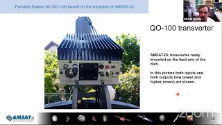
Portable station for QO-100 based on the modules of AMSAT-DL by Matthias DD1US.
A
The
next
presentation
I
will
give
myself-
I
will
show
you
a
portable
station
for
q100
assembled
from
components
from
the
amsa
dl
shop,
so
the
dun
converter
up
converter
the
modified
lnb,
and
this
will
give
us
about.
Therefore
it
will
take
about
45
minutes.
So
we
should
be
on
time,
hopefully
to
then
also
be
able
to
have.
B
A
Externally
there
is
a
gps
antenna,
module
very
simple
antenna,
active
gps
patch
antenna,
and
we
can
also
connect
the
1.3
inch
oled
display
to
it
from
the
lmb.
We
get
the
two
downlink
signals
from
the
wideband
transponder
and
the
narrowband
transponder
wideband
transponder,
being
horizontally
polarized.
A
A
A
If
of
the
narrowband
transponder,
is
chosen
to
be
145
megahertz
the
down
converter,
module
can
be
per,
can
be
changed
to
different
higher
frequencies.
I
have
chosen
a
downlink
on
two
meter
and
uplink
on
70
centimeter,
because
you
will
never
have
your
harmonics
in
the
tx
falling
into
the
receive
path.
So.
B
A
Centimeters
up
link
in
up
converted
by
the
up
converter
to
a
2.4
gigahertz
signal
going
to
the
patch
antenna.
The
output
power,
normal
output
power
is
about
3
watts,
2.8
watts.
The
whole
setup
is
running
with
dc
voltage
between
9
and
15
volts,
and
we
have
some
auxiliary
ports
like
the
ptt
input
and
communication
port
output,
where
we
can
monitor
the
parameters
of
the
up
and
down
converter
I'll.
Come
to
that
later.
A
The
feed
I've
chosen
is
a
40
feet,
patch
of
the
year,
with
a
patch
antenna
for
transmit
and
a
circular
waveguide
for
the
receiving
on
tangible
hertz
with
a
went
on
rocket
because
I'm
using
an
offset
dish
and
for
offset
dish
with
higher
f2d.
It
makes
sense
to
add
a
lens
to
focus
your
beam
and
optimize.
The
radiation
pattern
of
your
feet
into
a
offset
dish
with
an
f2d
a
higher
than
0.4.
A
The
assembled
module
looks
like
this.
I
put
it
in
a
in
a
box
which
is
actually
something
I
found
in
my
drawers.
You
see
the
oled
display
in
the
front
and
yeah.
That's,
essentially,
all
the
modules
are
in
one
of
this.
In
one
of
the
such
a
box,
the
frequency
scheme,
the
precise
frequency
scheme,
is
shown
here
on
this
slide.
A
The
wideband
output
from
the
lnb
when
it's
operating
from
24
megahertz
reference
frequency
is
1132.5
megahertz.
The
down
converter
is
really
routing
this
signal
out
again
to
the
wideband
transponder
output,
so
that
you
can
connect
your
80
atv
receiver,
I'm
using
a
mini
tuner
directly
to
this,
the
narrowband
transponder
output
is
at
1129.5,
and,
as
I
mentioned,
this
is
down
converted
to
two
meter:
gps
input,
1500,
the
reference
frequency
output
and,
of
course,
the
transmit
output.
The
down
converter
with
the
gps
module
is
also
providing
the
reference
frequency
to
the
up
converter.
A
A
This
is
number
one.
The
the
gain
of
the
lnb
and
the
whole
down
conversion
scheme
is
pretty
high
higher
than
really
a
normal
radio
needs.
So
down.
Attenuation
here
does
not
really
degrade
your
receiver
performance
because
you
have
so
much
gain
in
front
and
if
I'm
unintentionally,
transmitting
in
the
rx
output,
this
attenuator
is
capable
of
handling
100
watts.
So
I've
tested
it.
You
can
never
damage
your
down
converter,
even
if
you
are
making
a
mistake
in
the
up
conversion
scheme.
A
A
A
A
If
we
look
on
the
this
is
a
measurement
of
the
whole
up
converter
and
you
see
that
the
input
is
at
430
megahertz.
I've
used
the
tx
in
low
port.
This
is
the
numbers
you
see
in
here.
P
p
in
is
at
the
tx
in
low,
and
you
see
the
output
power
here,
the
output
power
and
the
gain-
and
here
you
see
the
current
consumption.
A
B
A
A
Actually,
you
can
also
run
the
up
converter
all
the
time
you
can
make
a
short
here
and
run
it.
It
only
saves
you
a
little
bit
of
power,
but
it's
running
full
duplex
anyway.
So
if
you
don't
want
to
to
use
the
cable
to
your
trans
transceiver,
you
can
just
have
here
ground
this
and
you
will
have
the
pdt
on
all
the
time
the
oled
display
is
showing
you
here,
for
instance,
the
gps
data,
your
qth
locator
the
time
and
then
also
whether
your
transceiver
is
in
a
good
shape.
A
So
you
see
the
output
power
of
the.
If
the
receive,
if
is
in
the
two
meter
range,
the
lnb
is
supplied
with
24
megahertz.
We
see
12,
satellites
unlocked
and
the
precise
latitude
and
longitude
information.
The
communication
output
is
a
serial
output,
where
you
can
show
various
operating
parameters
in
a
remote
display.
You,
you
will
also.
I
don't
know
who
is
a
member
of
amsterdam,
but
if
you
have
seen
the
latest
journal,
we
also
have
some
information
about
how
to
use
this
com
output,
port,
for
instance,
by
a
web
server.
A
And
then
you
can
monitor
your
output
power,
various
conditions,
including
the
gps
information
we
have
on
off
switch.
We
have
the
power
input
9
to
15
volts
and
the
narrowband.
I
have
output
here.
Actually
on
this
picture,
there
is
one
connector
missing,
which
is
the
the
narrowband.
I
have
output
for
the
sdr,
which
I
added
later
so
I
missed
that
on
that
picture.
On
the
back
side
of
the
transverter,
we
see
the
white
band
input
where
we
get
the
signal
from
the
lnb
at
1132,
ish
megahertz.
A
We
see
the
wideband
if
output,
so
that's
internally,
routed
through
here,
you
can
connect
your
mini
tuner
or
whatever
you
prefer
to
receive
the
wideband
signals.
We
have
the
narrowband
input,
also
coming
from
the
lb
the
gps
antenna
input,
including
the
phantom
feed,
the
10
megahertz
reference
output,
which
I'm
using,
for
instance,
for
locking
my
ic
9700
to
the
transverter.
B
A
Picture
the
the
encasing
I
had
on
hand
has
a
large
heat
sink
and
all
the
components
you
will
see
the
inside
a
little
bit
later
are
mounted
on
this
heatsink,
though
there
is
no
need
for
a
fan
with
the
efficiency.
We
have
it's
fully
sufficient.
Also,
if
you
have
it
in
the
sun
to
run
it
without
any
active
cooling.
A
This
is
how
I
mounted
the
transporter
on
my
dish.
I've
mounted
the
arm
for
the
feet
upside
down,
you'll,
see
some
details
later,
and
so
the
cable
from
the
output
of
the
up
converter
to
the
feed
is
only
about
40,
centimeters,
so
very
little
losses,
and
so
it's
quite
convenient
to
have
it
there
yeah.
This
is
the
bottom
part,
and
now
we
look
inside
you
see
here
is
the
up
converter
part,
which
goes
to
the
antenna
port
for
the
for
the
putty.
This
is
the
down
converter
part.
A
Here
you
see
the
attenuators.
I
show
you
some
details
later
power,
splitter
limiter
and
then
the
front
with
the
with
the
with
the
display
and
the
user
interface
same
picture,
the
other
side,
I'm
using
mostly
a
semi-rigid,
cable
or
semi-flex
cables
because
of
the
nice
shielding
or
if
I
use
flexible,
cable,
double
sheet
that
cables
are
recommended.
A
Here
you
see
the
how
I
mounted
the
the
up
converter
to
the
heatsink,
I'm
using
a
copper
spreader,
so
a
copper
plate
under
under
the
up
converter
between
the
pc
board
of
the
up
converter
and
the
copper
spreader.
There
is
a
thin
layer
of
thermal
conductive
material
which
is
flexible,
but
it
brings
all
the
heat
from
the
pc
board
or
most
of
the
heat
from
the
pc
board,
down
to
the
the
copper
spreader,
and
so
the
converter
stays
pretty
cool.
A
A
Is
also
mounted
directly
onto
the
heatsink,
it's
not
absolutely
necessary
to
mount
the
up
and
down
converter
into
a
shielded
in
casing,
but
I
prefer
this
to
make
sure
there
is
no
un
unwanted
intercoupling
or
something
so.
I've
put
everything
in
shielded
boxes,
even
though
there
is
the
metal
encasing
outside,
of
course,
also
shielding
the
whole
setup.
A
There's
a
picture
with
the
with
the
two
boards
open
you
see
in
the
down
converter,
also,
the
gps
module
which
is
plugged
on
and
the
reference
frequency
output.
There
is
a
second
reference
frequency
output,
which
is
unused
but
terminated
with
a
50,
ohm,
resistor
and-
and
here
is
the
up
converter
board
with
the
power
management
dc
dc
converters.
B
A
The
antenna
port
because
of
this
90
degree
hybrids,
if
there's
a
reflection,
it
gets
absorbed
in
those
resistors,
the
two
tcx
os
on
the
gps
board,
as
well
as
on
the
down
converter
board.
I've-
it's
not
shown
here,
but
I
have
put
additional
foam
inside
before
I
put
the
lid
on
so
this
insulates
these
tcxo.
A
In
addition
to
make
it
very
thermal
stable,
it's
it's
no
big
deal,
but
I
recommend
to
do
this
and
to
make
sure
that
the
tco
drift
is
minimum.
You
know
the
short
term.
Variations
are
determined
by
the
tcxo
itself.
The
frequency
variations.
The
long
term
is
locked
by
the
gps.
The
gps
loop
from
the
gps
into
the
ocx
tcxo
by
the
pll
is
very
slow,
so
it
takes
several
seconds
to
lock
and
therefore,
short
term
variation
would
be
still
visible
on
your
output
signal,
or
you
can
see
on
your
receive
signal.
A
A
Teflon,
pc
board
cut
it
and
it's
just
50
ohm
input,
output,
traces
and
those
are
used,
as
I
mentioned
at
the
I
have
output
of
the
receiver
and
the
tx
input
from
the
transceiver,
so
that
I
cannot
harm
accidentally.
The
up
and
down
converter,
the
30
db.
Insertion
loss
is
pretty
precise
and
270
centimeter
and
also
the
input
return
loss
is
very
high.
So
this
also
helps
you,
because
your
transceiver
will
always
see
a
perfect
output
match,
so
no
problems
can
arise
by
mismatch
of
the
transceiver.
A
A
The
power
splitter
is
a
standard
mini
service
power.
Splitter.
You
can
use
different
ones.
This
one
is
pretty
small
and
I
have
built
I've
put
two
of
them
in
the
box,
one
to
split
the
receive
signal
and
feed
it
number
one
to
an
sdr
and
simultaneously
to
the
transceiver,
and
the
same
is
true
for
the
transmit
path.
A
Where
I
combine
the
input
signal
from
an
sdr
and
the
transceiver
to
the
input
of
the
up
converter,
the
insertion
loss
at
2,
meter
and
70
centimeters
are
measured
also
to
be
very
low
about
0.3
db
for
no
issues
there
as
you've
seen.
I've
also
put
the
oled
display
into
the
box.
It's
nicely
supported
by
the
firmware
in
the
down
converter.
A
There
is
an
I
square
c
interface
and
I
can
recommend
this
3d
printed
frame.
It
makes
it
very
simple
to
to
mount
this
display
onto
the
box.
There's
two
pieces:
you
put
the
oled
display
into
this
bigger
piece,
and
then
you
put
the
second
part
on
the
back
and
then
you
can
screw
it
to
the
front
plate
of
your
up
converter
or
transverter.
A
A
The
insertion
loss
really
doesn't
matter,
because
we
have
so
much
gain
in
the
down
converter
of
in
the
lmd
that,
even
if
you
lose
here
on
a
short,
cable
one
or
two
dbs,
it
doesn't
really
matter.
We
have,
I
think,
more
than
60
bb
of
gain
here.
You
see
the
the
putty
feet
with
the
the
lens
mounted.
This
ring
is
just
to
to
shift
the
whole
setup
into
the
tube
I'll.
Show
you
some
pictures
later.
You
can
see
here
an
adapter
from
the
waveguide
to
the
input
of
the
lnb.
A
A
friend
of
mine
has
a
cheat
machine
that
it's
made
from
brass
and
it's
soldered
onto
the
the
copper
wave
guide,
circular
waveguide
and
then
it's
it
has
a
taper
inside,
so
it
makes
a
transition
transition
from
the
slightly
larger
diameter
of
the
waveguide
of
the
putty
feet
to
the
thinner
diameter
of
the
lnb.
So
there's
a
taper
and
this
this
brass
piece
goes
into
this
into
the
waveguide
of
the
lnb.
A
It's
then
screwed
down
and
firmly
attached
and
yeah.
It
works
pretty
well
here
you
see
some
pictures
how
the
putty
feet
is
in
mounted
into
this
standard,
hd
pipe,
and
I
can
really
recommend
the
went
on
rocket
lnb
lens.
Those
lmds
are
very
cheap.
I
think
five
or
six
euros
just
by
the
whole
lmb.
It's
it's
a
dro.
A
A
A
This
is
shown
before
I
sealed
it.
Typically,
I
use
a
spinner
plus
2000
to
seal
the
connectors,
and
that
makes
it
waterproof
and
inside
you
see
the
connection
cables,
which
are
then
plugged
into
these
cables.
You've
seen
coming
out
of
the
lmb
respectively.
Here
is
an
end
connection
going
into
the
transmit
port
of
the
body.
A
The
putty
feet
shows
a
very
nice
match.
The
input
return
loss
is
about
124
db.
The
whisper
is
about
1.14,
so
pretty
nice
match.
You
can
also
see
here.
This
resonance
is
actually
the
effect
of
the
booty,
where
we
have
a
longer
side
here
and
the
shorter
side
here,
and
this
really
generates
the
circular
polarization,
because
we
have
a
rational
resonance
slightly
above
the
2.4
gigahertz
and
slightly
sort
of
slightly
below
and
slightly
above
and
at
2.4
gigahertz.
A
This
is
the
setup
now
in
my
backyard,
I'm
using
a
60
centimeter
offset
dish
from
cutline
and
you
can
see
the
arm
for
the
feet
is
mounted
upside
down,
so
there
was
no
water
coming
in
and
also
it.
The
transverse
is
mounted
here
on
the
back.
It's
actually
also
giving
a
pretty
good
balance
of
the
whole
setup,
I'm
using
a
battery
to
be
for
the
portable
operation
with
the
small
solar
cells,
which
is
buffering
it
and
an
ic
9700
it.
A
A
The
you
can
see
here
on
this
picture,
the
transfer
mounted
on
the
arm.
You
can
see
here
a
small
bracket
with
the
gps
patch
antenna
mounted
on
top
of
it
and
yeah,
so
there's
actually
no
interference
because
the
main
beam
is
going
out
here.
I
haven't
seen
any
problems
with
the
gps
antenna
being
influenced
by
the
transmit
signal
of
the
converter,
the
nice
thing
about
this
cutline
dish.
A
A
This
is
a
picture
of
the
received
signal
using
sdr
console.
You
can
see
the
beacon
signals
here,
the
psk
beacon
here
and
actually
you
can
see
even
the
signal
mario
mentioned
the
leakage
of
the
blue
toe
very
slightly
here.
So
the
setup
with
the
60
centimeter
dish
is
amazingly
sensitive.
You
don't
really
see
the
role
of
the
transponder
in
terms
of
the
transponder
noise,
so
that's
a
little
bit
low,
maybe
half
a
db
you
can
see,
but
also
the
uplink
signal
is
about.
A
My
uplink
signal
is
about
60p
below
the
beacon
level,
which
is
perfectly
fine
to
make
a
good
sideband
qsos.
So,
yes,
the
60
centimeter
dish,
I
I
believe
we
shouldn't
go
look
below
because
you
should
always
have
a
sensitive
setup,
but
it's
perfectly
okay
for
using
it
for
portable
operation
for
datv,
I'm
using
a
mini
tuner.
A
This
one
is
actually
from
batc
and
it's
connected
on
the
back
of
the
down
converter.
You've
seen
there
is
an
output
to
the
to
the
mini
tuner,
so
I
can
actually
also
watch
while
making
sideband
contacts.
At
the
same
time
with
the
pc
and
the
mini
tuner
watch
the
the
atv
downlink
it's
at
the
edge,
I
would
say,
because
the
dish
is
pretty
small,
but
I
show
you
some
picture
you
can
you
can
watch
d80
with
it
if
the
uplink
signals
are
strong
enough,
so.
B
A
A
This
is
oe
6k,
gkd,
transmitting
with
500
kilo,
samples
and
mer
4.5.
You
see
the
margin
is
very
low,
0.5
db,
so
if,
if
some
clouds
are
coming
up
or
so
you
will
always
already
lose
the
reception.
So
again,
the
60
centimeter
dish
is
really
only
recommended
for
portable
operation.
When
we
go
to
lower
sample
rates,
the
margin
gets
higher.
A
Here
you
see
a
signal
from
iw1
on
the
f
at
the
six,
any
rf6
and
the
margin
of
2
db
and
going
lower
or
at
similar
margin,
hb9
dug
with
250
kilo,
samples
of
8psk
signal
and
even
125
kilo
samples
from
0.5
afb
was
received
with
that.
So
to
simplify
a
little
bit
the
setup
I
decided
to
to
do
something
which
we
actually
have
done.
Amsa
dl
has
done.
A
Similarly,
in
the
setup
in
in
antarctica
means
reducing
the
cabling
between
the
transporter
and
the
transceiver,
and
I
modified
two
triplexers
because
they
have
really
pl
connectors
and
I
replaced
it
by
end
connectors,
but
essentially
you
can
route
them
over.
The
tripod
try
triplexer
the
received
signal
on
two
meter:
the
transmit
signal
on
70
centimeter
and
the
10
megahertz
reference
frequency
from
the
transverter
to
the
transceiver.
So
I
run
only
one
coaxial
cable
here
to
the
transceiver,
and
that
makes
the
whole
setup
very
easy
here.
A
You,
you
see
the
see
the
three
signals:
the
two
meter:
narrowband
output,
the
transmit
input
and
the
10
megahertz
reference
from
the
transceiver
from
the
transporter
going
through
the
triplexer
into
one
cable
and
on
in
front
of
the
ic9700
same
thing
happens.
We
get
the
signals
here
from
the
transcoder
and
split
it
up
again
into
those
three
signals.
A
A
As
I
mentioned
very
simple,
there
are
the
four
holes,
there's
oblong
holes
and
you
can
hang
in
and
attach
and
firmly
attach,
the
the
dish
to
the
to
the
wooden
box
and
inside
the
box.
You
can
see
that
the
whole
setup
of
the
mount
on
the
tripod,
including
the
transporter,
the
mini
tuner
and
the
feed,
is
all
assembled.
A
A
You
can
get
the
down
converter,
the
up
converter,
which
is
has
a
maximum
output
power,
6
watt
and
the
modified
lnb
on
the
amzr
shop,
and
I
would
like
to
give
a
special
thanks
to
stefan
delta
fox
8
golf
alpha,
charlie
and
kurt
delta.
Julia
zero,
alpha.
Bravo,
radio
for
developing
this
excellent
transverter
and
there
sometime
soon.
We
will
also
have
a
new
end
casing
for
the
up
and
down
converter.
A
So
if
you
are
a
little
bit
shy
on
doing
the
mechanical
work,
integrating
the
modules
into
a
in
casing,
we
will
offer
in
the
amsterdam
shop
already
made
in
casing
with
engraved
front
panel
and
all
the
the
holes
are
already
in.
Even
the
patch
cables
are
included,
so
that
will
make
life
much
easier
for
the
users,
and
I
would
like
to
thank
you
very
much
for
your
attention
and
let
me
check
on
the
transponder
and
also
on
the
youtube
whether
there
are
any
questions.
B
B
A
A
So
I'm
not
I'm
not
running
the
setup
in
the
rain.
Actually,
I
have
a
rundown
and
there
there's
a
little
bit
of
a
glass
over.
So
I
put
it
typically
there.
If
there
was
some
rain,
I
just
put
a
plastic
bag
on
top
of
it.
Then
you
can
still
use
it
because
I,
I
assume
you're
not
sitting
with
your
transceiver
in
the
rain
and
there's
only
one
coaxial
cable
needed
between
the
transverter
and
the
transceiver
and
the
the
length
actually
doesn't
matter.
B
A
A
A
A
Here
you
go,
you
see,
this
is
the.
This
is
a
total
current
consumption
without
the
ic
9700,
so
it's
up
and
down
converter
full
duplex,
so
at
2.5
watts,
output,
power.
Sorry,
this
is
at
a
6
watt
output
power
at
2.4
or
say
2
watts
to
3
watts,
output
power.
Current
consumption
is
roughly
1.3
amps
and
then
on
top
comes
your
transceiver.