►
From YouTube: A Shortened HF Antenna Michelle Thompson W5NYV
Description
QSO Today Academy September 2023 video recording of "A Shortened HF Antenna" by @MichelleThompsonAbraxas3D and ORI.
A
Greetings
all
I'm
Michelle,
Thompson,
w5nyv
and
I'm
here
to
talk
about
a
shortened
HF
antenna
project
from
open,
Research
Institute.
This
project
reflects
the
work
of
many
people,
the
design
dates
back
to
over
65
years
ago.
This
presentation
has
three
parts:
the
past
history
and
references
a
present
day
simulation
and
prototype
and
future
work.
A
A
A
You
may
know
about
the
Iron
Triangle
of
project
management,
where
you
have
budget
scope
and
schedule.
Quality
is
constrained
by
these
three
features.
You
might
have
heard
the
phrase
you
can
be
good,
fast
or
cheap,
choose
two
traditional
waterfall
product
development
fixes
the
scope,
and
then
the
budget
and
schedule
can
vary
and
balance.
A
Agile
projects
have
a
fixed
schedule
and
a
budget
and
the
scope
varies.
Antenna
design
has
a
similar
set
of
trade-offs
and
design
patterns
where
we
Balance
size,
bandwidth,
game
and
radiation
efficiency.
To
get
a
compromise
we
can
live
with.
How
do
we
reduce
the
size
of
antennas?
Well,
there's
three
major
ways
that
we
do
this.
We
can
modify
the
structure
physically,
we
can
use
electrical
components
or
lumped
elements
and
we
can
use
high
permittivity
materials.
A
Structural
modifications
can
be
divided
up
into
three
major
categories
slots
and
slits
fractals
and
meanders.
We're
going
to
use
meanders
lumped
elements
include
inductors,
capacitors
and
resistors.
You
have
probably
seen
a
capacitive
hat
or
a
coil
included
in
a
vertical
whip.
These
electrical
components,
change
the
electrical
length
of
an
antenna
and
dielectrics
are
high.
Permittivity
materials
can
move
the
resonant
frequency
of
an
antenna.
This
has
the
same
effect
as
changing
the
physical
size
of
the
antenna.
This
is
a
very
common
technique
with
antennas
made
with
printed
circuit.
A
Boards
meanders
provides
something
called
linear
loading
and
here's
a
great
web
page
by
m0pzt
who
describes
this
as
folding
the
wire
back
on
itself.
We
reduce
the
overall
length
of
an
antenna,
but
this
is
not
the
same
thing
as
an
inductor
or
a
coil.
This
is
one
of
the
earliest
papers
about
this
type
of
meander
dipole.
It's
from
the
radio
Society
of
Great
Britain
newsletter
in
1958..
The
article
is
by
MJ
heavyside
g2qm.
A
This
article
can
be
found
in
the
papers
directory
at
the
link
in
the
slide.
He
does
refer
to
the
folded
part
as
a
loading
coil,
but
to
be
very
clear:
we're
not
making
a
coil.
We
are
making
meanders
decades
later,
Monty
Northrop
n5ese,
designed
and
built
a
portable
hotel
room
friendly
version
of
this
antenna
and
published
a
fantastic
web
notebook
about
it.
A
Here's
a
drawing
of
what
he
built
and
used
and
here's
the
template
and
a
photograph
all
are
available
directly
from
Monty's
website,
and
we
captured
a
pdf
version
of
the
page
for
safe
keeping
in
the
project.
Github,
there's
a
pretty
strong
indication
from
the
papers
that
this
antenna
works
pretty
well.
Never
underestimate
old
newsletters
as
a
source
of
excellent
ideas
do
not
fail
to
write
down
the
things
you
experiment
with,
even
if
you
don't
have
the
time
to
do
a
perfect
job
or
a
complete
analysis.
A
A
A
First,
we
simulated
the
design
initial
results
from
the
Washington
DC
volunteers
and
MMA
were
good,
so
a
model
in
Matlab
was
written
and
published
we're
going
to
walk
through
that
model
and
explain
it.
We
then
constructed
an
antenna
using
the
dimensions
from
N5
ese's
documentation
and
finally,
we
took
initial
measurements
of
the
Prototype
and
we
present
them
here.
All
this
work
is
publicly
available
on
GitHub.
The
link
is
here.
A
The
structure
of
the
repository
is
shown
here
with
the
Matlab
based
model
and
results
in
One
Directory,
the
simulations
and
photographs
and
field
testing
from
the
Washington
dc-based
Volunteers
in
another
directory,
and
then
technical
articles
and
papers
in
the
papers
directory.
Now,
by
the
time
you
watch
this,
there
may
be
additional
directories
or
changes
to
the
directory
structure,
but
the
home
page
for
the
repository
will
explain
which
directory
is
what
we
called
this
project
dumbbell,
because
the
antenna
design
roughly
resembles
a
weight.
A
Lifter's
dumbbell,
we
start
out
by
duplicating
the
introductory
model
in
the
1958
paper,
so
we
can
get
a
decent
handle
on
the
theory.
The
model
has
an
aerial
length
of
256
feet
and
uses
sine
X
Squared
to
represent
the
radiated
power
of
short
sections
of
a
half
wave
antenna.
The
x-axis
is
the
electrical
distance
from
the
free
end
and
the
area
under
the
curve
represents
the
radiation.
Resistance
of
the
part
of
the
aerial
represented
by
that
part
of
the
Curve
sine
X
Squared
is
an
easy
curve
to
plot,
but
labeling
the
graph
took
some
effort.
A
This
part
of
the
script
handles
the
labels.
Here
we
color
in
sections
of
the
curve
to
illustrate
the
points
made
in
the
paper.
Our
x-axis
is
expressed
in
radians
and
not
feet.
We
rotate
through
a
half
wave,
so
we
go
from
zero
to
Pi
radians.
This
makes
the
graph
more
General.
The
question
posed
in
the
paper
is
what
if
we
could
make
the
end
piece
in
cyan
act
like
the
middle
piece
colored
in
green,
we
get
much
better
radiation
resistance
in
the
green
section
than
in
the
cyan
section.
A
A
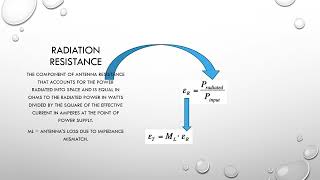
We
also
have
total
antenna
efficiency,
which
is
where
we
take
our
antenna
efficiency
and
then
account
for
the
power
loss
due
to
impedance
mismatch.
It
should
make
sense
to
you
that
you
want
as
little
friction
as
possible
for
those
waves
to
travel
from
the
radio
into
the
wire.
We
can
think
of
impedance
mismatches.
How
easy
it
is
to
open
a
door
to
leave
a
house.
You
can
lose
a
bit
of
momentum
or
power
if
you're
constantly
tripping
over
the
badly
installed
door
frame
on
the
way
out.
A
A
They
are
pretty
close
in
performance
if
you
measure
the
area
under
the
Curve
I
copied
over
N5
ese's
comments
from
his
page
to
the
comments
in
the
script
and
thought
about
them
for
a
while,
I
captured
the
antenna
length
of
his
notebook
and
10
as
a
variable,
just
in
case,
we
want
higher
radiation
resistance
while
being
shorter.
This
is
a
pretty
good
explanation
of
what
we're,
after
so
let's
model
his
design
in
Matlab,
build
it
and
test
it.
A
There's
a
lot
of
different
ways
to
model
things.
All
models
are
wrong
and
some
are
useful.
According
to
George
box,
he
was
yet
another
smart
British
person,
a
famous
and
accomplished
statistician
I,
decided
to
parameterize
this
design
by
starting
out
with
a
frequency,
calculating
the
wavelength,
dividing
it
into
six
parts
to
get
a
half
wave
dipole
segmented,
into
three
sections.
The
outer
two-thirds
would
then
be
folded
up
into
the
meanders.
A
Okay,
so
we
have
these
zigzags
and
we
keep
seeing
at
least
one
inch
gap
between
them
over
and
over
again
in
the
papers.
There
is
no
explanation
for
this
particular
value,
so
it's
another
thing
on
the
list
to
test
in
future
work.
If
any
of
this
sounds
like
fun
to
you,
then
welcome
aboard
Notch
length
was
set
to
an
inch
Notch
length
is
the
space
between
the
wires
in
the
zigzag
section.
A
So
it
was
an
inch,
but
we
have
to
use
meters
because
Matlab
uses
the
metric
system.
We
have
our
Notch
length
and
we
know
how
much
wire
we
want
to
fold
up.
We
want
it
to
be
kind
of
squarish
in
shape,
so
how
many
times
can
we
go
back
and
forth
if
we
zigzag
with
a
one
inch
Gap?
We
want
to
find
out
the
number
of
humps
in
the
folded
section
and
we
can
use
the
quadratic
equation
to
produce.
This
result.
Here's
the
Whiteboard
session,
where
we
figured
this
out.
A
Thank
you
to
lab
tech,
one
one
of
our
student
interns
for
doing
a
great
job.
Here
we
got
a
result,
but,
as
you
might
have
guessed,
it's
not
an
integer
number,
it's
something
like
5.34
humps
to
use
up
all
that
wire.
Now
we
want
the
wire
to
end
at
the
edge
of
our
rectangle
and
not
halfway.
There,
then
that
last
fold
won't
be
complete
if
we
don't
have
an
integer
number
of
of
humps.
So
who
knows
what
will
happen,
then?
A
Maybe
nothing,
but
we
want
it
nice
and
neat
with
a
small
and
we
can
make
it
nice
and
neat
with
a
small
extra
step.
We
set
the
number
of
humps
to
the
floor
of
the
value
we
just
calculated,
which
just
means
round
down.
Then
we
recalculate
the
height
and
width
the
folded
section,
while
keeping
the
spacing
between
the
wires
at
one
inch
so
not
too
bad
we're
going
to
make
a
bird
cage
style
structure
on
the
end
like
in
the
1958
paper
proposed
for
outdoor
use.
A
A
A
We
take
this
into
account
and
grow
the
disc,
a
tiny
bit
to
compensate
this
doesn't
matter
very
much
for
small
structures
like
what
we're
making
where
it's
about
a
foot
by
a
foot
for
the
folded
section,
but
for
larger
antennas
like
what
we'll
probably
need
for
160
meters,
it
might
make
a
difference
again,
something
we
can
play
around
with
in
future
work.
Now
we
take
our
calculations
to
matlab's
antenna
designer
the
Meander.
Dipole
model
looks
like
the
shape
we
need.
A
We
configure
this
model
with
our
calculated
measurements
and
then
show
our
results
using
functions
and
visualizations
in
matlab's
RF
toolbox.
First,
we
show
the
physical
model
of
the
antenna
hey
so
far,
so
good.
Next,
we
convert
the
basic
model
to
a
wire
stack
model.
This
moves
the
model
from
the
original
printed
circuit
board,
Trace
model
style
to
a
wire
antenna
model
with
the
right
type
of
feed.
Point:
here's
the
wire
stack
with
a
close-up
of
the
folded
section.
A
Antenna
pattern
looks
reasonable,
but
the
efficiency
really
doesn't
it's
a
line
across
the
top
reading,
one
here's
the
charge
density
with
a
lot
at
the
feed
point
and
at
the
very
end
of
the
wire
here's,
the
current
density,
which
made
me
feel
a
lot
better.
Seeing
that
that's
what
I
expected
here's
a
detail
of
the
current
density,
Paul
Williamson
kb5mu
asked
for
a
Smith
chart
as
a
digital
signal
processing
person.
This
is
kind
of
outside
of
my
comfort
zone,
but
there's
no
time
like
the
present
to
learn
how
to
do
something.
So
here
it
is.
A
This
is
over
23
to
28
megahertz
because
it
looked
like
that
was
an
interesting
part
of
the
simulation
we
all.
We
only
had
coax
to
work
with
at
first,
so
we
learned
how
to
add,
coax
transmission
line
to
the
model,
pretty
neat
we
make
a
coax
model
and
then
treat
it
as
a
load
on
the
antenna
we
then
simulated
SWR.
A
Finally,
we
used
a
really
nice
bit
of
animation
for
the
Matlab
Community,
which
was
posted
in
the
forums
the
code
and
the
helper
function
are
a
are
also
in
the
Repository.
Okay
enough
talk.
Let's
build
first,
we
need
some
spacers
to
lace
up
the
folded
part
of
the
antenna,
I
used
open
s-cad
and
our
calculated
Dimensions
to
make
an
STL
model.
A
These
are
in
the
Repository
as
well.
Thank
you
to
Mark
Whittington
for
3D,
printing,
these
spacers
and
suggesting
that
an
inch
thick
was
Overkill.
It
does
work
better
at
half
an
inch
thick
laser
cut.
Acrylic
is
another
way
to
do
this.
We
used
PVC
pipe
to
support
the
antenna
wire.
The
spacers
could
go
over
the
PVC
pipe
and
then
get
pinned
into
place.
A
Then
the
wire
can
be
laced
back
and
forth
and
secured
at
the
End
by
anchoring
it
through
a
hole
in
the
spacer
and
a
nut
and
bolt
there
wasn't
anything
in
this
design
to
prevent
it
from
rotating,
but
my
fetty
ham
friends
on
mastodon.radio
were
of
the
opinion
that
it
probably
wouldn't
matter
much
and
to
go
ahead
and
try
it
out
with
a
friction,
fit
and
straight
pins,
and
they
were
right
if
you're
looking
for
an
inclusive
and
friendly
Mastodon
server
mastodon.radio
is
a
great
fit.
It's
been
the
best
amateur
radio
social
media
experience.
A
A
We
in
this
case
gives
me
lab
tech,
one
and
Paul
Williamson
kb5mu
and
a
big
thank
you
goes
to
my
family,
who
saw
me
less
than
usual,
while
all
of
this
was
going
on,
putting
the
Mast
and
boom
together
with
a
trust
to
hold
up
the
PVC.
Otherwise,
it's
a
bit
droopy
test
fitting
the
cowlings
and
the
boom
went
well,
here's
how
the
pinning
was
done.
This
was
done
with
heavy
copper
wire
and
a
drill
lacing.
A
The
wire
went
pretty
well,
although
we
did
get
a
bit
too
enthusiastic
with
the
second
one
and
crunched
the
spacer
into
the
PIN.
We
took
it
back
off
and
rotated
it
to
avoid
the
damage
we
did
and
then
laced
it
back
up.
The
interior
of
the
print
is
honeycombed
and
not
solid.
This
is
a
prototype
and
not
something
that
should
be
deployed
long
term.
A
This
means,
if
we
put
this
up,
it
will
stay
up
temporarily
for
like
five
years.
You
all
know
the
drill
here.
It
is
up
and
connected
with
coax,
because
that's
what
we
had
on
hand,
we
knew
it
would
behave
well
near
22.,
something
megahertz,
so
we
picked
the
closest
band
to
that
connected
it
up
to
a
Flex
radio
and
did
a
side-by-side
comparison
to
a
40
foot
vertical
in
the
same
location.
A
Here's
the
results.
We
took
a
little
side
trip
with
a
nano
VNA,
the
SWR
curved
looked
like
the
one
in
Matlab,
and
maybe
the
Smith
chart
does
too.
But
all
three
of
us
are
digital
Communications
people.
We
were
thrilled
just
to
get
something
that
didn't
look
like
cotton
candy.
On
the
monitor
we
found
out.
You
can
use
the
Nano
VNA
to
find
out
the
length
of
your
coax.
A
So
we
did
that
and
I
was
able
to
update
the
Matlab
model
with
the
exact
length
of
coax
this
sort
of
feedback
between
reality
and
a
model
is
super
fun
and
it
improves
the
model
in
the
process.
We
had
an
intermission
due
to
Hurricane
Hillary.
We
brought
the
dumbbell
inside
and
suffered
only
minor
damage
to
two
trees,
thanks
to
John
barcraft
k6
am
we
got
some
twin
lead
Paul
swapped
in
the
Twin
lead
for
the
coax
and
then
Paul
did
some
archeology
and
uncovered
his
helicopter's
tuner.
A
A
A
This
was
not
a
stable
platform
for
installation,
but
served
pretty
well
to
get
Nintendo
up
for
in
the
air
for
testing.
As
long
as
the
wind
doesn't
blow
very
hard,
the
other
stuff
we
had
in
stock
or
we
got
from
open,
Research
Institute
first
really
grew
after
I
shared
the
initial
results,
a
special
thank
you
to
n0mql
and
n6cta
for
their
advice
and
encouragement,
one
of
the
most
fun
things
about
any
paper
or
project
is
the
future
work.
A
A
So
an
antenna
that
can
do
160
meters
is
the
next
Target.
Several
people
are
drawing
up
plans
and
working
on
it,
and
I
can't
wait
to
help
support
that
and
to
build
a
prototype
here
in
San
Diego,
in
addition
to
the
optimizations
concerning
the
folded
wire
spacing
and
exactly
how
much
shortening
can
you
get
away
with?
A
We
need
to
figure
out
why
Matlab
thinks
the
efficiency
is
one.
So
maybe
you
know-
and
you
can
explain
it
to
us,
so
we
can
add
that
to
the
script
and
the
spacer
design
can
be
improved
too.
Using
the
winding
wire
over
toothed
gears
approach
is
okay,
but
lacing.
The
wire
through
holes
in
a
disc
would
improve
the
alignment
and
make
it
look
neater
and
a
notch
to
fit
over.
The
pin
would
secure
the
disc
with
respect
to
rotation,
so
we
have
a
saying
at
Ori.