►
Description
This talk is by Andre Souto (subscribe to his YouTube at https://www.youtube.com/channel/UCqKVoVhkMJdDF4ThSSQ_vZw) presents a high level of the project then dives into how baseband scrambling, BCH encoding and LDPC encoding have been implemented. It also provides information about the how the DVB-S2 specifies these components.
A
Hi
everyone
thanks
for
joining
the
session.
My
name
is
andres
otto
and
I'll
make
a
deep
dive
of
the
dvbs
2
encoder
implementation
for
fpga,
one
of
the
things
we've
been
doing
at
phase
four
and
firstly,
I'd
like
to
thank
michelle,
w5
and
yv
for
all
her
phase.
4
work
ron
w6rz
for
all
his
amazing
new
radio
work,
without
which
this
rcl
implementation
would
would
have
been
way
way
harder.
A
I
also
need
to
mention
thomas
and
shu
and
paul
for
their
contributions
and
help
as
well
and
before
we
dive
in.
Let
me
provide
some
context
by
going
over
essentially
three
questions:
what's
the
scope
of
the
dvb
s2
encoder
how
to
interact
with
it
and
how
does
the
system
looks
like?
So
what
is
the
scope?
This
is
the
function
block
diagram
as
it
appears
in
the
dvbs2
spec
and
I'm
gonna
start
at
the
end
of
this
diagram.
A
The
remaining
parts
make
up
a
regular
axis
stream.
Okay,
the
output
interface
is
very
similar,
but
without
the
frame
based
parts.
At
this
point,
the
data
has
been
modulated,
and
so
it's
going
to
have
inq
components.
Essentially,
besides
input
and
output
streams,
we
also
have
one
axillite
interface
for
memory
maps
register
space
access.
A
We
can,
for
example,
check
how
many
frames
in
flight
we
currently
have,
or
what's
the
biggest
smallest
frame
that
has
passed
through
a
certain
stage,
and
we
can
also
block
a
data
stream
for
debug
and
allow,
for
example,
a
word
at
a
time
or
a
frame
at
a
time
and
to
check,
for
example,
how
the
system
behaves
the
input
and
output
streams.
Timing
diagram
looks
like
this.
In
this
example,
we
can
see
an
input
frame
configured
as
short
frame
qpsk
and
quadrate
1
4..
A
This
is
what
I
mean
when
I
say:
frame
parameters
are
constant
for
a
frame
during
data
transfer,
and
the
last
part
I
want
to
show
on
the
quick
intro
topic
is:
how
does
the
system
looks
like
this
is
a
high-level
block
diagram
of
the
encoder
itself
as
it's
implemented
in
rtl,
and
it's
very
similar
to
the
functional
block
diagram
we've
just
seen
these
red
blocks
here
are
instances
of
the
axis
stream
debug,
which
is
the
block
I
mentioned
before.
That
allows
us
to
monitor
and
control
the
flow
of
data.
A
A
Every
block
in
the
system
looks
similar
to
this,
and
most
dvb
specific
stuff
will
also
have
frame
attributes,
but
we
can't
really
change
them
like
this,
because,
for
example,
this
green
block
here
has
nowhere
to
get
data
attributes
from
so
to
support
every
frame
having
a
different
configuration.
We
need
to
transport
this
configuration
alongside
the
frame
itself,
and
we
do
this
by
using
a
axis
stream.
Tid
interface
and
essentially
stid
carries
arbitrary
data
to
mtid.
A
A
We
can
use
this
to
transport.
Anything
that's
constant
during
the
frame,
and
that
makes
it
very
simple
to
connect
multiple
components
you
can
see
in
the
top
level
here,
the
frame
configuration
input
is
encoded
into
a
vector
and
that's
how
it
gets
transported
and
to
other
blocks
in
the
design-
and
this
concludes
the
basics
really
so
time
to
get
into
the
cool
stuff
and
we're
going
to
start
with
the
baseband
scrambler,
and
this
is
a
great
first
block
to
look
at
because
it's
very
straightforward
with
few
design
decisions.
A
A
The
spec
also
provides
a
diagram
that
is
actually
very
close
to
the
rtl
implementation.
We
have
a
15
bit
shift
register
and
every
time
you
get
a
bit
at
the
input
data
in
this
shift
register
will
move
from
the
left
to
the
right.
We
take
bits,
14
and
15.
Add
them
together
to
get
the
new
value
of
bit
1.
to
get
the
output
bit.
We
take
lfs
our
bit
1
and
xor.
Slash,
add
with
the
input
bit
and
then
we're
ready
to
get
the
next
bit.
A
Looking
at
the
block
diagram,
we
can
see
that
the
baseband
scrambler
is
quite
simple
and
we
have
the
lfsr
here
that
is
reset.
Just
like
I
described,
and
that's
going
to
happen
when
the
design
as
a
whole
is
reset
or
during
operation
when
stlas
is
asserted,
and
that
indicates
that
a
frame
has
completed.
A
So
we
reset
the
value
to
prepare
for
the
next
frame
bit.
1
is
then
xored
with
input
data
and
that
will
produce
the
output
data.
So
remember,
I
said:
there's
few
design
decisions
right
here.
I
chose
to
register
the
ports
and
but
when
making
this
presentation,
I
realized
it's
actually
better
to
move
this
to
outside
and
register
as
needed
and
leave
the
baseband
scrambler
doing
only
what
it's
supposed
to
do
but
never
mind.
A
Next,
we
have
the
fak
encoding
subsystem,
which
is
made
of
three
components:
the
bch
encoder
ldpc
encoder
and
the
bt
interleaver.
So
dch
encoding
takes
a
baseband
frame
as
an
input
and
depends
a
parity
check
to
that.
The
size
of
this
parity
check
code
is
given
indirectly
in
the
spec,
and
the
size
is
going
to
depend
on
the
frame
length
and
the
code
rate.
A
The
size
of
the
bb
frame
is
given
in
the
bch
uncoded
block
column
here
and
to
get
the
size
of
the
bch
backward.
We
do
bch
coded
size,
minus
bch,
uncoded
size
and
to
calculate
the
actual
parity
check
code.
We
use
a
set
of
polynomials
and
then
we
use
frame
length
and
code
rates
to
identify
which
polynomial
index
to
use
and
this
index
will
then
identify
with
the
polynomial
itself.
A
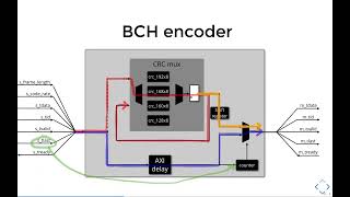
This
block
has
a
constant
latency
so
to
make
our
life
easier,
and
we
add
this
extra
stream
delay
to
the
data
stream
here
at
the
bottom,
to
make
both
data
and
crc
code.
Words
arrive
at
the
same
time
in
the
output
modes.
So
it's
simple
to
choose
which
one
we
want
to
forward
and
the
crc
max
has
no
back
pressure,
which
means
we
only
really
need
to
tap
off
data
to
it,
and
we
don't
need
to
replicate
the
streams
here.
A
Data
and
parity
check
code
are
multiplexed
when
the
input
frame
completes
and,
and
we
need
a
counter
to
count
how
many
bits
the
parity
check
code
needs
to
fit.
The
output
data
with
the
counter
essentially
helps
the
shift
register
here
to
slice
parity
check
code
into
data
with
chunks.
If
that
makes
sense,
we
can
look
at
this
by
looking
at
the
flow
of
data
right
and
so
the
baseband
frame
flows
to
the
output
and
through
the
crc
max
and
once
st
last
is
asserted,
indicating
the
input
frame
completed.
A
A
A
This
is
the
text
for
the
encoding
process,
as
it
appears
in
the
spec,
but
I
figured
it
might
be
maybe
a
little
too
boring
if
I
just
read
this.
So
what
I'll
try
to
do
instead
is
show
you
how
the
process
looks
like
in
a
minute
or
so
we
start
with
the
data
frame.
This
data
frame
has
a
certain
length
and
for
this
example,
it
doesn't
matter
really
what
the
length
is,
but
the
spec
defined
the
frame
as
having
kldpc
bits.
A
A
Each
data
bit
will
be
xored
with
values
pointed
by
offsets
given
by
the
parity
bit
address,
table
and
essentially
each
group
of
360
bits
and
we'll
use
one
row
from
the
parity
bit
that
is
stable
like
this,
and
so
the
first
bit
of
the
first
group
will
use
row
zero
and
I'm
gonna
put
some
numbers
to
help
us
visualize.
Okay,
bit.
Zero
will
then
be
added
that
is
xored
in
offsets
three
five,
seven
and
eleven.
A
A
A
A
A
I'm
gonna,
divide
and
conquer
the
ldpc
encoder
is
actually
made
up
of
two
sub
components:
the
ldpc
table
in
the
ldpc
core
and
the
ldpc
table
essentially
unrolls.
The
parity
bit
addresses,
which
means
it
deals
with
selecting
the
correct
base
parity
bit
address,
table,
given
the
frame
length
and
the
code
rate,
and
it
will
track
groups
of
360
bits,
adds
q
to
the
offset
correctly
and
so
on,
and
the
ldpc
core
actually
does
the
parity
calculation
itself,
and
so,
let's
have
a
look
at
the
ldpc
table.
A
First,
so
first
of
all,
a
dedicated
module
makes
testing
ways
simpler
and
faster,
and
next,
if
we
go
through
the
dvb
spec
appendix's
bnc
will
find
21
tables
and
each
one
has
a
variable
number
of
coefficients,
but
in
total
that
is
almost
here,
six
and
a
half
thousand
and
coefficients,
and
we
need
16
bits
to
represent
them
as
we've
seen
previously.
We
need
to
unroll
the
tables
and
we
need
to
do
that
on
the
fly,
because
if
we
start
the
unrolled
values,
it
would
be
just
way
too
much.
A
Data
to
start
internally
here
are
four
examples
of
how
tables
actually
look
like
in
the
spec.
These
are
all
for
normal
frames,
but
the
short
frames
ones
are
very
similar.
So,
let's
zoom
in
in
the
first
one
we
can
see
it
has
two
sections:
the
top
one
has
12
rows
of
15
values
and
the
bottom
one
has
30
rows
of
three
values.
A
So
let's
have
a
look
at
how
this
works.
This
is
an
example
of
a
table
yeah,
it's
small,
just
to
keep
stuff
simple.
Okay,
what
we're
gonna
do
is
put
the
table
content
in
one
memory
and
its
size
and
in
another
memory
and
the
tables
themselves
are
always
flattened
by
the
way
and
to
read
this
flat
memory
region.
We
need
to
know
basically
where
the
table
starts,
the
shape
of
the
top
region
and
the
shape
of
the
bottom
region.
A
So,
let's
say
the
next
table
looks
like
this
again.
We
split
stable
data
from
the
table
size
and
like
with
the
previous
table.
We
need
to
know
where
this
table
starts
the
shape
of
the
top
and
the
shape
of
the
bottom
section,
and
we
keep
doing
this
for
all
21
tables
to
actually
unroll
the
table.
We
we
also
need
the
value
of
q,
so
we
add
this
to
the
metadata
table.
A
In
summary,
the
coefficients
rom
has
around
100
kilobits
worth
of
data
and
it
uses
seven
block
ram
18
on
xynx
fpga.
The
metadata
memory
is
much
smaller
only
around
one
kilobit
and
it
will
likely
be
mapped
to
lookup
tables,
so
piecing
everything
together,
frame,
type
and
code
rate
address
the
metadata
table.
The
metadata
table
outputs,
the
relevant
info
to
the
unroll
logic.
The
unroll
logic
reads:
the
parity
address
table
to
generate
offsets
for
the
ldpc
core
calculation
and
the
unraw
logic
here
is
just
a
bunch
of
nasal
counters.
A
A
Besides
the
coefficients,
the
ldpc
table
generates
an
output
called
m
next,
which
marks
the
end
of
a
row
that
is
a
new
bit
can
be
processed,
and
this
means
that
this
period
here
corresponding
to
offsets,
3,
5,
7
and
11,
are
related
to
bit
0
and
then
the
following
period
corresponds
to
bit.
1
then
bit
2
and
so
on.
A
A
The
accumulation
logic
uses
offsets
from
the
ldpc
table
to
xor
data
in
the
associate
positions
of
the
parity
rim.
While
that's
going
on
it
will
keep
the
output
mux.
Selecting
data
from
the
axis
stream
replicate.
That's
the
baseband
plus
bch
fact
passing
through
once
the
input
frame
completes
it
will
switch
to
receive
data
from
the
post
frame
accumulation,
slash
with
conversion
blocks.
A
The
frame
ram,
uses
a
block
ram
internally
and
block
ram's
data
width
is
naturally
16
bits
technically
18
bits
because
ecc
but
anyway,
that's
why
we
have
this
width
converter
from
16
to
n,
to
convert
parity
data
to
the
output
data
width.
The
ldpc
input
sync
is
used
to
synchronize
table
offsets
to
data
bits
because
parity
bit
offsets
are
given
one
per
cycle.
We
need
to
convert
the
input
data
stream
to
one
bit
as
well.
This
ensures
that
output,
data
and
output
offsets
are
synchronized.
A
Data
passes
through
the
width
converter
directly.
Offsets
pass
through
literally
directly
output
will
be
valid
when
both
width,
converter
and
table
have
data.
The
system
is
ready
to
consume
data
from
the
width
converter
when
the
ldpc
table
indicates
next
and
the
reader
is
ready
to
consume
this
data
as
well.
We
can
consume
an
offset
from
the
ldpc
table
whenever
there
is
a
valid
data
bit
and
the
reader
is
ready
to
consume
this
data
bit
as
well.
A
A
A
A
A
However,
this
two-cycle
latency
also
applies
between
write
data
and
read
data,
and
this
is
an
issue
in
cases
where
we're
reading
data
from
an
address-
that's
been
written
less
than
two
cycles
ago
and
write
data
won't
make
it
in
time.
This
is
called
a
data
hazard
and
it
does
happen
in
some
tables
in
some
coefficients.
A
A
A
Unfortunately,
this
session
time
is
up,
even
though
there
is
still
more
to
cover
this
session
only
covered
baseband
scrambler,
bch
encoder
and
ldpc
encoder,
but
there
is
plenty
of
interesting
blocks
too.
If
there
is
enough
interest,
I
can
cover
those
in
the
future.
I
would
like
to
share
the
current
state
of
the
project,
though
we
have
verified
all
84
valid
configuration
combinations
in
both
simulation
and
hardware,
using
new
radio
results
as
a
baseline,
and
this
includes
varying
configuration
on
a
per
frame
basis,
and
we
don't
need
to
stop
data
flow
change
parameters
then
restart.
A
Although
there
are
some
caveats,
we
also
have
a
continuous
integration
pipeline
running
on
github.
That
runs
tests
on
gnu,
radio
plus
ghdel
and
some
tests
with
uses
if
you're
not
familiar
ghdl,
is
an
open
source.
Vhdl
simulator
and
the
os
is
an
open
source.
Rtl
synthesis
suite
we're
currently
bringing
up
an
over-the-air
setup
to
test
against
lab
equipment
in
ori
lab
west
located
in
san,
diego
california,
and
that's
the
image
on
the
left.
A
Michelle
and
paul
have
been
doing
an
amazing
job
in
the
lab.
I
am
trying
to
get
more
time
to
help
them
out
and
I'm
sure
we
can
get
this
setup
up
and
running
with
lab
gear,
commercial
gear
and
that's
gonna,
be
an
incredible
milestone.
I'm
I'm
sure
there
will
be
some
issues.
I
mean
there's
always
issues,
but
we
are
making
progress
and
that's
great.