►
From YouTube: 20220205 ORI Technical Advisory Committee Meeting
Description
Jump to:
M17 - CODEC2 work https://youtu.be/dou6hyj7SIc?t=86
M17 - Beyond RRCs https://youtu.be/dou6hyj7SIc?t=2263
M17 - Module 17 https://youtu.be/dou6hyj7SIc?t=2580
OpenRTX - RC-1 Board https://youtu.be/dou6hyj7SIc?t=2766
P4DX - End to End Demo progress https://youtu.be/dou6hyj7SIc?t=4677
Remote Labs - Polar Codes with MATLAB workflow https://youtu.be/dou6hyj7SIc?t=7306
A
C
Okay,
so
hello
again
greetings.
My
name
is
wojciech
kaczmarski
and
I'm
the
current
project
lead
in
m17
project
and
also
I'm
a
hum
radio
operator
under
the
call
sign,
sp5wp
okay,
so
we
can
get
started
and
today's
presentation
is
about
quantizer
optimization
for
codec2
and
codec2
is
based
on
lpc,
linear,
predictive
coding.
So
it's
a
very
popular
framework
for
voice
coding.
C
Codec2
is
free
to
use
and
open
source
voice.
Codec
that
has
been
developed
by
david
rowe
vk5,
dj,
dgr
and
david
is
also
a
ham
radio
operator
and
a
lot
of
mostly
hum
radio
operators
helped
him
in
development
that
voice
coder
and
we
are
going
to
focus
on
the
full
rate
mode,
which
is
3200
bits
per
second,
and
it
gives
already
a
good
quality
voice,
but
not
as
good
as
it
can,
as
we
will
see
later.
C
C
C
So
this
is
a
mathematical
model
for
the
speed
generation,
and
this
is
how
speech
signal
looks
like,
and
this
is
a
sample
from
our
community
manager,
edward
wilson
and
2xddd,
saying
probably
m17,
and
this
is
a
sample
of
his
voice.
So
we
see
that
there
is
a
difference
between
vowel
sounds
and
sibilance,
because
sibilants
have.
C
C
We
call
that
unvoiced
speech
so
like
saying
like
s
or
f,
that's
unvoiced
speech
and
then
there's
a
fragment
of
voice
which
is
voiced,
and
you
can
see
clearly
that
the
zero
zero
crossing
number
is
decreased
and
the
pitch
is
visible
and
the
pitch
is
just
the
difference
between
those
samples
right
here.
So
it's
the
fundamental
frequency
for
this
fragment
and
you
can
see
that
it
changes
over
time.
C
C
Now
the
mathematical
model
tells
us
that
you
can
use
an
excitation
source,
which
is
just
either
a
pulse
train
for
voiced
sounds
like
a
or
a
or
you
can
have
a
random
source
of
random
signal.
I
mean
a
noise
signal
that
is
filtered
to
produce
sibilance
like
s
or
f,
and
then
we
have
signal
output,
which
is.
A
C
A
time
series
of
some
values
now
the
filter
that
is
mathematic
mathematical
model
of
the
vocal
tract
can
be
approximated,
with
an
oppo
digital
filter
of
order
p
and
usually,
and
in
codec
2.
The
p
is
equal
to
10,
so
we've
got
up
to
five
four
months.
You
can
represent
up
to
five
four
months
so
four
months
I
will
get
back
to
this
later.
So
this
is
the
filter.
C
C
And
there
are
10
parameters,
a
10
coefficients
for
each
frame,
so
you
have
to
compute
autocorrelation
values
for
the
speech
frame
and
then
use
a
recursive
algorithm
called
levinson
darbin
algorithm
to
solve
a
set
of
linear
equations
to
obtain
a
parameters
from
the
speech
sample,
and
this
is
how
it
looks
like
and
the
blue
one,
the
blue
curve
or
piecewise
linear.
But
let's
say
it's
a
curve.
C
The
blue
plot
is
the
discrete
fourier
transform
of
the
speech
input
and
you
can
see
that
the
red
curve
is
approximating
the
spectral
envelope
of
the
signal
and
the
red
curve
is
actually
the
frequency
response
of
the
a
of
that
filter.
Sorry
h
of
that
filter,
which
we
just
modeled
right
here
so
first
we've
got
the
speech
frame.
Then
we
extract
a
parameters
from
that
frame
and
it
gives
us
a
filter
like
this.
C
So
to
describe
this
red
curve,
we
use
10
a
parameters
coefficients,
and
this
is
a
polynomial
representation
of
the
vocal
tract
and
its
filter.
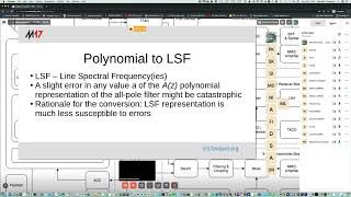
Now
the
other
method
of
describing
the
filter
is
to
use
line.
Spectral
frequencies
called
lsf
for
short
now
when
we,
if
we
want,
if
we
wanted
to
transmit
parameters,
a
coefficient,
a
from
one
place
to
another
of
an
rf
link
or
something.
C
So
this
is
that
plot
again
that
red
curve-
and
you
can
see
that
those
dashed
lines
represent
line
spectral
frequencies
and
they
come
in
pairs
because
when
we
say
let's
say,
let's
assume
that
this
is
the
frequency
response
of
a
letter
a
or
a
phoneme
r,
because
this
this
is
not
a
letter.
This
is
a
phoneme.
C
We
can
see
that
for
our
brains,
it's
important
to
it's
important,
to
have
all
those
bumps
in
the
right
places,
so
those
bumps
are
called
formants
and
using
10,
lsf's
or
5
lsps.
When,
where
lsp
is
line,
inspector
pair,
you
can
represent
5
up
to
5
formats,
and
you
can
see
clearly
that
this
plot
has
four
the
first
one
is
very
pronounced,
because
those
two
lsf's
are
very
close
together.
C
So
the
closer
together
are
those
lsf's,
the
higher
the
peak
is-
and
this
is
the
second
one.
This
is
the
third
one.
This
is
very
less
very,
not
very
pronounced,
and
there
is
also
one
here
which
is
almost
invisible,
but
it's
right
here.
It's
because
those
two
lsfs
are
very
far
away
from
each
other,
so
to
have
good,
intelligible
voice.
C
You
have
to
know
where
each
formant
is,
but
the
formant
is
just
the
bump.
Remember
you
have
to
know
where
the
bump
is,
how
high
is
the
peak
and
that's
that's
pretty
much
it
for
intelligible
voice
and
also
it's
good
to
have
this
valley
as
low
as
possible.
So
the
one
of
the
limitations
of
the
lsf
representation
of
the
spectral
envelope
of
the
signal
is
that
this
valley
is
not
low
enough,
but
we
can
do
anything
about
it
using
a
line
prediction
coding,
a
linear
prediction
coding.
C
So
right
here,
on
the
right
hand,
side,
we've
got
a
dc
component
and
we
go
right
up
here
when,
where
we
have
the
nyquist
frequency
so
somewhere
about
here,
we've
got
two
kilohertz,
because
the
nyquist
frequency
is
four
kilohertz.
This
is
just
because
the
most
used
sample
rate
in
audio
processing
is
speech.
Processing
is
eight
kilohertz.
That's
the
standard.
D
C
C
C
It
subtracts
the
input
from
every
codebook
entry
and
sees
what's
the
difference
between
them
and
picks
the
one
that
is
the
closer,
the
closest
one,
the
input.
So
in
our
case,
it's
150
and
of
course
we
don't
transmit
that
it
was
150.
We
just
transmit
the
index
of
that
entry.
So
in
our
case
it
would
be
six.
C
So
that's
for
the
ls
f1,
the
first
lsf,
so
we've
got
nine
more
to
go
and
next
one.
Well,
the
next
step
works
like
this.
We've
got
lsf,
it
should
say
lsf,
but
david
row
uses
names
like
this,
so
I'm
consistent
with
that,
so
the
first
lsf
was
quantized
to
the
value
of
150
hertz
instead
of
145,
which
was
the
original
one.
C
C
C
C
How
to
generate
a
good
codebook
so
to
generate
it?
We
have
to
obtain
a
long
sample
of
speech
and
that's
called
speech
corpus,
and
there
are
already
prepared,
like
tens
of
gigabytes
of
speech,
which
can
be
downloaded
for
free
and
used
for
free,
and
one
of
the
examples
is
open.
Slr
and
ted
lion
is
a
part
of
open
slr.
As
far
as
I
know,
and
I
have
used
those
to
generate
code
books
for
collective
improvements.
C
I
think
I'm
going
to
skip
this
for
a
second
okay.
So
let's
take
a
look
at
the
lsf2
minus
lsf1
difference
distribution.
So
this
is
a
probability
density
function
of
this
difference
and
you
can
see
that
the
most
probable
value
is
around
100
hertz.
For
this
difference
and
the
second
plot,
those
points
represent
codec2
reference
code
book,
which
is
the
dlsp1
from
this
slide.
C
C
You
can
use
the
fact
that
some
values
have
more
probability
of
appearance
than
the
other,
and
you
can
see
that
values
above
500
hertz
have
very
low
probability
of
appearance.
So
it's
pretty
much
a
waste
of
time
and
waste
of
bits
to
have
all
of
these
code
book
entries.
So
it's
better
to
have
less
code
book
entries
here
and
focus
on
this
part,
which
has
really
good
chance
of
appearance.
C
The
next
method
is
moving
to
vector
quantizer,
so
the
previous
part
used
one
dimensional
quantizer
called
the
scalar
quantizer,
where
we
had
lsf's
from
one
to
ten
and
each
lsf
was
encoded
separately.
So
we
didn't
have
to
group
them
into
let's
say
three-dimensional
or
four-dimensional
vectors
and
in
vector
quantizing.
We
do
that.
So,
first
of
all,
we
have
to
group
all
10
lsfs
into
three
groups,
and
the
first
group
is
the
lsf
from
one
two
three
then
from
four
to
six
and
from
seven
to
ten,
so
the
first
vector
is
three-dimensional.
C
C
C
I
move
on
to
the
parts
that
are
sub
vectors
of
three
three
and
four
dimensions,
so
the
beta
location
for
the
proposed
quantizer
is
that
I'm
using
six
bits
for
the
course
code
book,
which
is
64
in
64
entries
and
then
four
bits
per
stage
for
the
split
vector
quantizer
and
it's
a
multi-stage
split,
vector
quantizer,
because
for
each
sub
vector
I've
got
either
three
or
four
stages.
It's
in
the
next
slide.
I
believe
so.
C
I've
got
three
stages
for
lsf,
one,
two,
three
four
stages
for
lsf:
four,
to
six:
to
get
a
better
approximation
for
those
lsfs
and
three
stages
for
the
last
four-dimensional
part
of
the
original
lsf,
and
this
gives
46
bits
per
frame
while
codec2
uses
50
in
its
original
scalar
quantizer.
And
this
is
how
it
looks
like
this
is
what
you
are
waiting
for.
C
So
this
is
a
set
of
64
10
dimensional
vectors,
which
you
we
use
for
the
course
search.
So
we've
got
a
10
dimensional
input
and
we
say
we
have
to
search
the
best
the
best
fit
from
this
set.
So
let's
say
it
was
the
first
one.
Then
we
split
this
vector
the
original
one
into
three
subparts
sub
vectors
and
the
first
one
is
three
dimensional,
so
lsfs
from
one
to
three.
C
C
C
C
C
C
C
A
C
C
The
spectral
distortion
is
reduced
because
codebooks
are
pdf,
optimized
and
pdf
is
the
probability
density
function.
So
it's
good
to
have
pdf
optimized
code
looks
as
it
minimizes
the
spectrum,
distortion
and
bitrate
doesn't
change,
because
we
still
have
32
code
books
and
52
entries
for
every
code
book.
C
C
So
you
have
to
have
really
good
headsets
headphones
to
notice
the
difference,
and
this
is
a
spectrogram
for
each
sample.
The
first
one
on
the
top
is
the
original
sample
from
m2xdd.
So
this
is
his
voice
and
you
can
see
that
most
of
the
energy
is
in
the
lower
frequencies,
so
below
one
kilohertz.
Even
now,
the
next
one
is.
C
C
C
Some
parts
might
be
reconstructed
better,
but
it's
pretty
much
hard
to
see
any
difference
on
the
spectrogram.
I
would
have
to
play
the
sample,
which
I
don't
have
right
now
it's
on
the
other
pc,
but
pretty
much.
It
looks
the
same
as
vanilla
contact,
2,
so
visually.
It
looks
pretty
much
the
same
now.
The
vector
quantizer
does
pretty
much
bad
job
right
here,
and
this
is
a
vowel
sound.
C
C
B
Thank
you
very
much
for
watching
all
right,
so
the
floor
is
open
for
a
short
amount
of
time.
It's
for
questions.
I'd
like
to
direct
technical
questions
to
the
chat.
That
would
be
the
good.
So
if
you
have
a
particular
technical
question
about
the
presentation,
you've
seen
go
ahead
and
post
it
in
chat
and
voice
will
answer
there.
E
C
E
B
Oh,
thank
you.
It's
wonderful
to
hear
okay
voice
check.
Please
monitor
chat,
to
see
if
anybody
has
some
questions.
They'll
probably
be
thinking
about
your
presentation
and
all
the
slides
and
the
the
video,
and
all
of
that
will
be
available.
We'll
do
our
very
best
to
to
make
sure
that
we
edit
and
record
and
present
all
of
this.
B
So
the
next
thing
on
the
agenda
is
the
m17
project.
It's
beyond
root,
raised
cosine
filters
and
what
we've
been
talking
about
doing
is
optimizing
filtering
for
m17
implementations,
because
m17
wants
to
take
full
advantage
of
resource
restricted
hardware
that
anything
that
can
be
done
to
make
the
the
rrc's
better
or
higher
performance
is
of
interest.
B
C
Okay,
so
I'm
not
very
familiar
with
this
topic,
but
I
know
something
about
it,
so
I'm
going
to
try
and
tackle
it.
So
the
problem
is
that
when
you
have
to
transmit
stream
using
fsk,
it's
very
wise
to
filter
the
base
band
so
that
it
doesn't
occupy
infinite
bandwidth,
because
imagine
that
you
would
have
to
transmit
a
stream
of
zeros
and
ones
using
fsk.
C
And
let's
say
this
is
just
a
simple
two
fsk
method.
So
you've
got
frequencies,
f0
and
f1.
So
if
you
just
switch
from
one
to
the
other,
you
would
get
a
lot
of
frequency,
spectral
splatter,
let's
say
so.
It's
very
wise
to
first
filter
out
the
bit
stream.
So
those
transitions
take
more
time
but
less
than
the
symbol
symbol
time,
and
this
is
what
we
use
in
m17
and
actually
we
use
root,
raised
cosine
filter
for
that
purpose.
C
So
when
the
basement
is
formed,
we
just
take
the
bit
stream
input,
upscale,
it
probably
10
times
and
then
apply
root,
raised
cosine
filter
at
the
transmitter
and
the
same
thing
applies
to
the
at
the
receiver
side.
So
for
the
we
just
take
the
the
modulator,
the
modulator
output
from
the
radio
and
then
apply
the
same
filtering
at
the
receiver.
A
C
It
doesn't
have
very
good
performance
when,
compared
to
some
other
that
has
been
pro
has
been
proposed
by
someone
on
twitter
and
someone
proposed
that
a
modified
parks,
mcclellan
method
might
be
used
to
obtain
a
filter
which
has
the
same
performance
but
uses
less
tabs,
and
with
that
it
means
that
it
requires
less
computational
complexity
and
does
the
same
job.
Basically,
so
the
proposal
is
to
use,
modify
modified
park,
smack
method
to
obtain
new
tabs
and
use
them
both
at
the
transmitter
and
receiver
side.
B
Oh,
thank
you,
I
think
that's
a
very
solid
summary
all
right,
so
we'll
follow
up
later
on
with
probably
a
more
expanded
presentation
on
this
particular
topic,
because
we've
really
just
only
started
looking
at
it
any
questions
from
a
like
an
advisory
point
of
view.
Please
go
ahead
and
ask
them,
and
if
there's
any
technical
questions
about
this
particular
part,
then
put
them
in
the
chat.
D
D
What
are
they
called
the
the
md
380
radios
are
using,
so
a
lot
can
be
reused.
What
has
been
been
written
for
that
and
yeah
so
currently
what
you?
What
the
idea
is
for
these
ports
is
that
you,
you
connect
a
a
speaker
mic
to
it
and
use
that
to
to
transmit,
but
the
the
goal
for
for
the
final
revision
is
to
have
something
in
in
this
form
factor,
maybe
maybe
a
bit
bigger
than
so.
This
is
the
usual
kenwood
style.
Speaker
mic
to
yeah
have
a
board
in
here.
D
B
F
F
F
F
F
The
various
radio
devices
we
are
going
to
to
support
and
a
final
goal
could
be
that
we
we
want
to
to
have
a
software
platform
which
can
be
used
as
a
base
for
ham,
radio,
experimentation,
which
is
something
that
is
really
lacking
in
my
opinion,
because
the
the
great
part
of
the
hammer-
radio,
let's
say
andy
talk-
is
or
mobile
radios.
They
feature
a
proprietary
software
which
cannot
be
modified
and
there
have
been
some
some
attempt.
But
right
now
it
was
missing.
I
mean
a
great
software
platform
to
experiment
and
dock
icon.
F
F
Next,
we
we
would
like
to
also
extend
the
support
to
jaisu
ft
1ft2d
radios,
which
are
pretty
cheap
and
and
well
build.
So
this
extending
the
support
to
these
radios
would
be
great
and
also
in
the
future.
We
would
like
to
to
see
our
some
new
hardware,
some
radio
built
from
scratch
to
to
better
suit
the
the
experimentation.
F
Okay,
we
have
to
talk
about
hardware,
implementing
protocols,
some
radio
protocols
in
hardware
or
in
software,
because
there
is
an
important
difference.
Most
radios
there
we
see
on
the
market,
like
probably
any
dmr
radio
they
employ.
They
implement
the
dmr
protocol
in
a
hardware
way,
which
means
that
there
is
a
dedicated,
baseband
chip.
F
You
see
this
is
the
basemanship,
the
hrc
5000,
which
is
used
on
the
md,
380
radio
and
basically,
in
these
types
of
radio.
We
have
this
chip,
which
does
implements
fully
the
dmr
protocol
well,
except
for
the
vocoder,
which
is
strangely
done
by
the
mcu,
and
the
the
most
important
part
about
this
picture
is
that
the
microphone
and
the
speaker?
F
F
The
the
main
microcontroller
has
no
way
to
receive
the
basement
signal
or
to
even
to
output,
some
some
audio
to
the
to
the
speaker,
because
it's
all
handled
by
a
dedicated
chip
so
but
unfortunately,
the
dedicated
ship.
Just
does
the
dmr
and
if
we
want
to
do
n17
with
our
radio,
we
need
to
work
around
this
limitation.
F
What
what
we
have
done
so
far
is
to
research,
some
hardware,
modifications
which
add
the
missing
audio
paths
to
the
to
this
radio.
Basically,
we
add
the
mcu
the
capability
to
receive
and
transmit
arbitrary
audio
signals
over
the
radio,
and
we
had
the
ability
to
receive
microphone,
input
and
transmit
speaker
output.
F
F
So
we
want
to
create
a
really
minimal
module
and
we
want
to
give
it
a
standardized
interface
so
that
it
has
some
connectors
and
you
know
how
to
interface
with
this
module,
and
the
idea
is
to
use
this
core
radio
module
on
multiple
application,
some
of
it.
Some
of
these
may
be
an
nd
talk
for,
for
example,
or
a
mobile
radio,
or
just
fitting
it
into
a
laptop
to
have
a
radio
modem
into
a
laptop
or
otherwise.
F
So
the
idea
is
that,
if,
if
you
want
to
experiment
with
other
protocols,
you
should
be
able
to
do
and
while
from
the
radio
features
a
point
of
view,
we
want
to
target
the
vhf
and
uhf
band
because
they
are
the
the
most
widespread
and
widely
used
band
in
their
ham,
radio
scene.
I
think,
and
also
we
want
this
module
to
have
a
low
power
output
and
the
optional
external
amplifier,
because
limiting
the
module
to
to
being
low
power.
F
F
F
And
finally,
here
are
the
the
three
open
points
which
are
questions
to
which
we
haven't
found.
Yet
an
answer.
The
first
of
all
is
the
silicon
shortage
problem
that
causes
basically
the
microcontroller.
We
have
selected
the
radio
chip
which
are
hard
really
hard
to
obtain,
and
this
has
a
in
sort
of
discouraged
us
to
commit
to
complete
the
schematic
and
to
do
production,
because
if
we
cannot
buy
one
of
the
two
main
chips,
we
cannot
even
let's
say,
build
the
final
prototype
other
than
that
we
are.
F
This
is
still
being
debated
and
also
we
we
have
some
doubts
about
the
the
adf
7021
usability
in
in
this
application,
because
wojciech
has
has
designed
a
development
board
for
this
radio
chip,
but
he
still
hasn't
got
some
promising
results
from
it.
So
we
still
are
not.
We
are
not
sure
100
percent
sure
that
this
radio
chip
is
suitable
for
our
application.
B
E
The
federico
the
excellent
presentation
very
interested
in
the
project
question
I
have
for
you,
you
mentioned
the
desirability
for
compatibility
with
the
m2
b
slot,
typically
used
by
the
wlan
or
the
wi-fi
part
of
the
circuit
board,
I'm
not
sure
which,
but
my
concern
is
the
antenna
generally.
I
wouldn't
think
that
the
wlan
or
wi-fi
have
the
correct
antenna
design
built
into
a
laptop
for
vhf
or
uhf
signals.
Do
you
envision
any?
E
F
In
particular,
the
b
key
I
was
mentioning
is
the
one
used
by
the
modem,
like
a
cellular
modem
in
laptops
and
usually
laptops
that
have
how
do
you,
let's
say
a
predisposition
for
this
kind
of
modems.
They
also
include
antennas
cellular
antennas,
which
are
usually
placed
in
the
laptop
screen
and
the
cables
end
up
near
to
the
modem
slot,
but
I
think
that
definitely
we
can't
use
these
built-in
antennas
because
they
are
tuned
to
be
in
the
range
of
cellular
networks.
F
So
this
point
of
placing
an
antenna
in
a
usable
position
for
the
radio
card
inside
the
laptop
is
still
a
problem
which
we
haven't
figured
out
yet,
but
I
think
there
are
two
possibilities.
A
first
possibility
is
to
use
a
pigtail
connector
that
plugs
into
the
radio
card
module
and
you
can,
let's
say,
bring
it
outside
your
laptop,
maybe
using
a
hole,
for
example
the
kensington
hole
for
for
the
keychain,
and
this
way
you
will
have
a
connector
outside
this,
your
laptop,
which
may
be
a
solution.
B
F
B
F
Okay,
okay,
but
oh
wait
just
realized
that
we
actually
have
either
look
at
it.
It
is
a
really
cool
chip
because
it
integrates
a
microcontroller
and
a
ax
5043
radio
chip.
So
it's
a
like
a
combined
microcontroller
and
a
radio
chip,
and
this
is
very
cool
because
it
will
let
us
complete
the
radio
card
with
a
single
chip
instead
of
two,
but
since
the
chip
it
includes
to
use
to,
let's
say,
transmit
analog
fm.
F
C
Thank
you.
I've
got
some
experience
with
ax
5043
and
it
looks
like
it
can
run
something
that
I
would
call
a
vco
mode,
so
it
it's
able
to
transmit
continuous
life,
and
it
has
two
differential
inputs,
just
adcs
that
can
be
fed
with
base
band,
and
I
have
already
confirmed
that
m17
works
in
takes
mode
on
that
chip,
but
the
problem
is
that
the
receiver
part
it's
not
very
good,
because
the
output
level
is
either
very
low
or
is
very
quantized.
B
F
C
B
E
F
G
G
Anyways,
we
are
targeting
narrowband
protocols
with
low
data
rate
for
now
that,
because
it
simplifies
the
choice
of
the
the
radio
module,
but
if
basically
an
application
for
a
higher
data
rate
comes
into
mind,
we
can
still
either
study
the
the
use
case
or
try
to
derive
a
different.
Let's
say
designer,
using
similar
components.
G
B
All
right,
fantastic,
okay:
we
are
ahead
of
schedule
and
we
have
presenters
that
will
be
here
in
about
43
minutes,
it'll
be
1100
hours,
my
time,
u.s
pacific.
So
it's
open
discussion.
The
room
is
open
and,
and
please
feel
free
to
hang
out.
We
will
resume
our
formal
presentation
schedule
at
1100
pacific
and
thank
you.
What
we'll
do
next
is
talk
about
the
end
to
end
demonstration
for
phase
four
dx
or
p40x.
B
B
Once
those
signals
are
transmitted
up
to
the
to
payload
or
to
ground
sat,
then
it
is
turned
into
a
dvb
s2
signal,
a
time
division,
multiplexing
signal
down
on
10
gigahertz,
so
there's
plenty
going
on
with
fpga
development
and
demonstrations
and
all
sorts
of
fun
things
with
vorader
correction.
After
that
is
a
discussion
about
our
work
on
we're,
anticipating
work
on
polar
codes.
B
These
are
very
exciting
codes
and
there's
lots
of
peril
in
working
with
them
because
they
are
also
used
in
5g.
So
we
have
plenty
of
patent
issues
to
to
look
at,
and
some
regulatory
and
legal
efforts
to
to
clear,
but
our
intent
in
order
to
support
the
technical
side
of
this
is
to
enable
a
matlab
workflow,
so
that
people
in
universities
that
are
working
on
a
publishing
in
polar
code
area
will
be
have
some
familiar
resources
at
remote
labs.
B
B
B
B
B
B
B
J
J
The
current
implementation
starts
with
the
stream
adaptation
here.
So
the
scope
of
the
encoder
as
of
today
is
the
baseband
scrum
scrambler
fact:
encoding
beats
mapping
physical
layer
framing
and
modulation
right
now
we
don't
have
padder
or
physical
layer,
signaling
or
pilot
insertion,
and
but
we
do
plan
to
insert
to
add
those
as
well.
J
J
J
J
The
timing
of
the
of
input
and
output
looks
like
this,
and
in
this
example,
the
input
frame
is
configured
as
short
frame,
qpsk
code
radon
for
one
fourth
and
the
receiver.
Sorry,
the
encoder
received
this
and
at
some
point,
is
gonna
write
to
the
output
frame
and
by
the
way
this
is
what
I
mean
when
I
say,
parameters
are
constant
during
the
frame
as
in
the
values
in
the
ports
are
constants.
While
data
has
been
transmitted.
J
J
J
Anything
that's
constant
during
the
frame,
and
that
makes
it
simple
to
connect
multiple
components,
and
so
this
is
like
the
top
level,
and
you
can
see
that
the
frame
configuration
here
is
encoded
into
an
sdid
vector
and
that's
how
it's
transported
throughout
the
design
so
yeah.
This
concludes
the
intro
stuff
and
so
stepping
into
the
baseband
scrambler,
and
so
the
baseband
scrambler
is
it's
a
nice
first
block
to
look
at
first,
because
it's
very
simple.
J
J
So
the
spec
provides
a
diagram
that
is
very
close
to
the
rtl
implementation
and
like
this
is
the
15
bit
shift
register
and
data
moves
from
the
left
to
the
right.
Every
time
a
data
bit
comes
in,
and
so
we
take
bits
14
and
15
and
end
them
and
sorry
and
add
them
together
and
to
get
the
new
value
of
bit
one
and
to
guess
the
output.
J
We
only
we
only
need
to
xor
bit
one
of
the
lfsr
with
the
data
input,
so
the
block
diagram
is
simple
and
we
have
the
lfsr
with
an
initial
value,
and
so
the
lfsr
is
going
to
be
reset
when
the
system
is
reset,
as
in
the
master,
reset
or
power
on
reset
or
when
st
last
t-last
is
asserted,
and
that
indicates
this
frame
completed.
So
we
reset
the
lfs
argument.
Preparation
for
the
next
frame
bit
0
then,
is
xor
with
the
input
data
that
produces
the
output
data
and
yeah.
J
J
The
size
of
the
bb
frame
is
given
in
this
sort.
The
size
of
the
bb
frame
is
given
in
the
this
column,
which
has
it
it's
essentially
bch
encoded
block
and
the
size
of
the
effect.
The
bch
fact
code
word
is,
then
you
know
the
difference
between
the
bch
coded
block
and
the
bch
uncoded
block
and
to
actually
calculate
the
parity
and
the
parity
check
code.
We
use
this
set
of
polynomials
and
so
frame
length
and
code
rate
identify
which
polynomial
index
should
be
used,
and
this
in
turn
identifies
the
polynomial
itself.
J
J
So
when,
when
data
arrives
at
the
output
max,
you
know
it's
easy
to
choose
where
to
which
one
to
output,
and
also
the
crc
max
block,
has
no
back
pressure,
which
means
this
dashed
line
is
literally
like
a
tap.
We
don't
need
to
replicate
streams
and
manage
back.
Pressure
is
just
literally
tapping
off.
J
J
Yeah
the
baseband
frame
flows
through
the
output
directly
and
through
the
sears
through
the
crc
block.
So
yes,
the
crc
max
and
once
stlast
is
asserted
indicating
that
the
input
frame
completed.
We
count
the
number
of
words
needed
to
shift
data
from
the
crc
flip-flop
to
the
output
through
the
shift
register.
B
J
So
we
start
with
a
data
frame,
so
this
data
frame
has
a
certain
length
and
for
the
matter
of
this
example,
the
length
doesn't
matter,
but
the
spec
refers
to
this
as
kldpc,
so
this
frame
is
divided
into
360
bits
in
groups
of
360
beats
each
and
and
the
parity
bits
will
be
stored
in
a
memory
that
I'm
gonna
call.
Parity
memory
in
each
data
bit
will
be
x,
stored
with
the
values
pointed
by
offsets
given
by
the
parity
bit
address
table.
J
So
each
group
of
360
bits
will
use
one
row
from
the
parity
address
table
like
this,
so
the
first
bit
of
the
first
group
uses
row
zero
and
I'm
so
I'm
putting
some
numbers
just
so.
These
are
arbitrary
numbers
and
just
to
help
visualize
and
so
bit.
0
will
be
added.
That
is
xor
in
offsets.
3,
5,
7
and
11..
J
The
second
bit
also,
you
also
uses
row
0,
but
we
add
q
to
the
offset
and
q
is
a
an
integer
that
is
function
of
frame,
length
and
code
rate,
and
for
this
example
let's
say:
q
equals
three.
So
for
bit
one
the
offset
is
going
to
be
three
plus
three,
so
six,
five
plus
three
seven
plus
three
and
then
eleven
plus
three.
J
J
J
J
J
So
the
lgpc
encoder,
so
I'm
gonna,
divide
and
conquer
right.
So
there's
a
the
ldpc
table
that
is
responsible
for
essentially
unrolling
the
table.
So
it
will
pick
the
correct
base
table
and
add
q
appropriately
track.
The
360
bits
group
and
all
of
that
and
essentially
will
prepare
the
beat
addresses
and
the
ldpc
core
will
do
the
actual
calculation.
J
Well,
there
is
21
tables,
there
is
varying
number
of
coefficients
in
each
table,
but
essentially
there's
like
six
and
a
half
thousand
coefficients
and
each
coefficient
is
16
bit
wide
so
and
we
also
need
to
unroll
the
tables
on
the
fly
like
we
one
of
the
alternatives
I
consider
was
basically
unrolling
the
table
and
then
storing
that,
but
it's
prohibitively
really
prohibitively
big.
So
it
it's
not
feasible.
J
J
The
next
table
looks
it's
looks
similar,
so
12
20
by
12
and
then
12
by
3
and
yeah.
The
next
one
is
the
same,
but
36
by
12
and
72
by
three,
and
in
fact
all
tables
have
two
sections
and
the
number
of
rows
and
columns
is
constant
in
each
section
and
we
can
use
this
store
advantage
to
build
a
generic
table
reader.
J
And
how
that
works
is
so
suppose
this
is
a
table,
I'm
just
keeping
it
small
to
you
know,
keep
simple
so
we're
separating
the
shape
into
one
side
and
sorry
the
data
in
one
side
and
the
shaping
in
the
other
side,
and-
and
you
know
when
we
separate
the
data
we
flatten
them-
we're
gonna
see
in
a
second
how
that
looks
like.
So,
if
I
have
a
memory
that
has
this
somewhere,
I
need
to
know
where
this
the
table
starts.
J
What's
the
size,
the
shape
of
the
first
region
and
the
shape
of
the
second
region
and
suppose
another
table
looks
like
this,
we
do
the
same
and
again
we're
gonna
need.
You
know
where
disables
we
we
need
to
know
where
this
table
starts
and
this
the
shape
of
the
of
the
first
region
and
then
the
shape
of
the
second
region
and
yeah.
We
keep
doing
this
for
all
tables
and,
in
the
end,
oh
sorry,
to
unroll
the
table.
J
We
also
need
the
values
of
q,
and
so
they
sort
of
feature
fit
naturally
in
the
metadata
table,
as
well,
so
to
unroll.
So,
in
the
end,
we're
going
to
have
offline
and
parity
address
tables
placed
continuously
in
one
room
and
all
the
metadata
is
stored
in
a
much
smaller
room
and
the
net
result
is,
you
know
the
parity
bit
address.
Table
memory
is
around
100
kilobit
and
it's
gonna
use
seven
block
ram
18s,
which
is
good.
It's
not
not
bad
devices.
J
J
So
if
how
this
works
in
hardware,
so
frame
type
and
code
rate
address
the
metadata
table,
the
metadata
table
outputs
the
relevant
information
to
the
what
I
call
the
unroll
logic
and
then
religion,
bro
logic
will
use
this
information
to
read
the
coefficients
from
the
parish.
The
address
table
and
enroll
them
to
generate
the
final
offsets.
J
J
J
J
So
once
the
input
frame
completes,
it
will
switch
to
receive
data
from
the
post
frame
accumulation,
slash
with
conversion
the
frame
ram,
yeah.
The
parity
ram,
sorry
uses
a
block
frame
internally
and
block.
Oh
sorry,
yeah
yeah
and
block
rims
data
width
are
naturally
16
bits
technically
18
because
dcc
but
yeah
review
16..
J
J
The
accumulation
process
is
sort
of
the
heart
of
the
encoding
and,
to
this
block
connects
directly
to
the
input
synchronizer
and
here
offsets
are
used
to
read
the
parity
ram
and
because,
and
each
ram
address
holds
a
16
bit
value.
We
divide
the
offset
by
16
and
use
the
remainder
of
the
division
to
select
which
bit
of
the
read
data
we
need
to
operate
on,
essentially
so
within
xor
that
input
data
with
the
appropriate
bit.
It
writes
the
result
back
to
memory
and.
J
J
So
if
we're
reading
from
an
address
written
in
the
previous
cycle,
we
can
do
the
same
with
data
after
the
first
flip-flop
and
likewise
for
reading
an
address
written
in
two
cycles.
I
go
with
them
the
second
flip-flop
and
then
anything
later
than
this
or
over
two
cycles.
Data
will
just
come
from
the
block
ram
itself,
and
that
is
it
really
like
that
I
put
like
yo.
I.
B
J
J
So
currently
we
we
have
verified
in
simulation
and
hardware
and
all
84
valid
configuration,
combinations
and
we're
bringing
up
the
over-the-air
setup
and
by
the
way,
so
michelle
and
paul
are
doing
most
of
the
work
here.
I
wish
I
had
more
time
to
help
at
this
image
on.
The
right
is
my
is
my
local
setup
and,
and
that
is
it
really
so
I
put
links
you
know
getting
involved,
yes,
yeah
contacts
for
myself
and
well.
This
is
not
a
typo
right.
B
H
B
You
have
any
follow
up
later
on
know
that
this
will
be
if
all
goes
well.
This
is
recorded
and
will
be
edited
up
and
up
later
today,
and
you
can
continue
to
reach
out
and
ask
questions
about
what
you've
seen
but
I'll
turn
the
floor
over
to
anybody.
That
would
like
to
ask
any
or
give
any
advice
or
have
any
advisory
input
or
any
high-level
questions.
And
then
please
ask
any
technical
questions
in
chat.
E
G
E
J
J
E
You
can
recorrect
so
how
much
latency
is
in
the
spectrum,
because
we're
doing
that,
in
other
words,
you're
holding
up
the
data
that
you
have
not
transmitted
until
you
calculate
the
forward
error,
correction,
bits
and
then
sending
the
forward
error
correction
bits.
First
and
then
the
data
is
that
part
of
the
spec.
That's
adds
that
it
adds
latency.
J
B
Yeah
any
any
sort
of
manipulation
of
the
data
you
send
out
over
a
link,
you
always
run
into
adding
latency
and
that's
a
big
trade-off
with
any
sort
of
digital
signal,
processing
or
error.
Correction
coding
is
how
much
latency
are
you
adding
so
so?
Yes,
it
is
a
factor
and
the
one
of
the
things
that
we
do
in
this
particular
implementation
is
to
use
the
short
codes
in
or
a
short
frame
instead
of
long
in,
in
order
to
kind
of
address
some
some
latency
issues.
So
the.
A
B
J
A
B
A
E
C
B
B
All
right,
I
think,
let's
we'll
give
the
florida
to
thomas
perry
to
talk
about
his
advisory
opinions
today
and
but
feel
free
every
everyone
else
to
ask
questions
and
then
we'll
we'll
close
with
a
short
discussion
about
plans
for
polar
codes
and
the
matlab
workflow
in
remote
labs.
So
thomas,
you
have
the
floor.
I
B
No
I'd
like
to
to
to
highlight
that
that
we
we
are
moving
as
quickly
as
we
can
to
to
prove
out
all
of
our
designs
over
the
air.
Our
bias
is
that
it
doesn't
work
until
it's
transmitted
over
the
air
or,
like
you
said,
over
coax,
and
fortunately
we
can.
We
can
transmit
over
the
air
in
remote
labs
and
we're
getting
there.
B
B
The
development
board
that
we
are
using
is
the
adrv
9371,
and
this
fits
onto
a
ultra
scale.
Xilinx
fpga
development
board
called
the
zc706,
and
these
this
equipment
is
available
for
for
anyone.
That
wants
to
do
this
sort
of
work
over
the
internet
through
remote
labs
at
open
research
institute,
and
so
that's
what
we're
provided
and
what
we're
supporting
and
the
the
status
right
now
is
that
we
have
made
a
whole
lot
of
progress
in
incorporating
and
integrating
the
ip
block
into
the
reference
design
from
from
analog
devices.
We're
not
yet
transmitting
over
the
air.
B
We're
working
through
lots
of
different
scripting
to
properly
integrate
all
of
this
work,
and
we
anticipate
being
able
to
do
this
is
over
there
as
soon
as
possible.
The
first
way
that
we
tried
to
do
it
was
to
take
the
reference
design
and
follow
the
how
to
integrate
your
ip
core
into
our
stuff
from
analog
devices
ran
into
a
little
bit
of
trouble
there.
B
So
so
that's
that's
a
that's
one
front
of
progress
and
then
what
swatu
did
is
to
start
with
his
block
and
then
to
pull
in
the
reference
design,
and
we
had
some
interesting
tools.
Issues
with
that
vivado,
which
is
the
ide
that
we're
using
we
used
2019.1,
because
that's
the
the
latest
released
version
for
the
reference
design.
So
we've
run
into
some
interesting
tools,
issues
problems,
but
every
day
you
know
these
are
the
things
that
you
have
to
deal
with
and
solve
for
for
sort
of
a
complex
ide,
an
ecosystem
like
this.
B
B
You
know,
look
at
look
at
what
you
get
on
the
other
end
using
lab
gear
commercial
lab
gear.
So
if
you
want
to
learn
more
about
that,
it's
those
all
the
gear
is
listed
on
the
remote
labs
section
of
the
open
research
institute
github.
So
when,
when
we
publish
this
I'll,
have
the
link
directly
to
that.
B
E
Great
I'm
interested
in
these
projects
for
terrestrial
use,
aerial
drones,
for
example,
and
and
they
can
be
sort
of
as
the
technology
improves,
their
velocities
will
be
increasing
and
there
brings
in
doppler
shifts,
and
you
certainly
have
that
with
a
satellite,
but
what
is
sort
of
which
is
and
you're
going
to
be,
I'm
sure
you're
going
to
be
resilient
on
with
regards
to
doppler
shift.
The
question
I
have
is
just
the
data
rates
that
you're
expecting
and
actually
the
use
of
the
dvd
for
data.
B
Yes,
actually
dvb.
The
organization
has
a
protocol
that
we're
using
called
generic
stream
encapsulation
or
gse,
and
this
is
a
drop-in
replacement
for
for
mpeg,
and
so
that's
that's.
Our
eventual
goal
is
to
to
use
gse
generic
data.
So
what
that
gives
you
is
a
as
it
says,
generic
generic
stream
or
generic
data,
and
you
get
to
you
get
back
some
of
the
overhead
that
you
spend
on
broadcast
mpeg
stream
and
in
terms
of
data
rate,
the
data
rate
changes
with
respect
to
to
what
coding
and
modulation
you
do.
B
You
know
whatever
what
your
environment
or
what
your
channel
is,
or
what
your
stations
in
your
population
of
users
have.
Some
people
will
have
powerful
stations.
Some
people
will
not.
Some
people
will
have
a
pointing
error.
You
know
microwave
pointing
is
a
you
know.
Some
won't
some
are
moving
and
some
won't.
This
particular
set
of
protocols
is
resilient
to
doppler
and
is
is
good
for
that.
B
We
ran
through
the
numbers
all
the
way
up
to
leo
and
then
so
I
think
mike
parker
was
here
a
little
earlier
and
he
is
using
dbbs2
on
cat
sat
10,
megahertz,
10
gigahertz
down
link
in
the
amateur
image
part
of
the
band
and
is
is
doing
so
so
we've
been
working
and
and
collaborating
with
him
over
the
past
couple
of
years
about
that.
So
that's
that's.
A
good
proof.
Application
for
for
dvbs2
on
in
space.
B
B
E
B
Yeah
traditionally,
the
control
part
of
the
satellite
would
be
outside
of
the
traffic
band,
but
we've
actually
talked
about
including
it.
So,
yes,
the
the
you
would
as
soon
as
you
have
a
an
implementation
that
you
can
start
testing,
then
you
start
looking
at
things
like
like
latency
and
timing
and
and
all
of
that
so
so
yeah.
That's
that's.
Definitely
on
the
docket.
B
What
we
have
been
using
for
for
matlab
is
the
home
license,
which
is
150,
is
an
excellent
deal,
but
it
does
not
include
hdl
coder
or
gpu
coder
or
matlab
coder
and
those
are
the
heterogeneous
processing
types
of
toolboxes,
and
so
there's
a
couple
of
things
that
I'm
sure
a
lot
of
you
are
thinking.
It's
like
well,
why
in
the
world,
would
you
go
with
matlab
and
not
an
open
source
tool
flow,
because
octave
is
wonderful?
B
There
isn't
really
a
replacement
for
simulink
and
some
of
the
things
that
we
want
to
do
don't
exist
in
the
open
source
tool
flow.
Yet
so
there's
a
two-pronged
approach
here.
This
is
to
allow
open
source
work
and
polar
coding
to
happen,
and
we
do
need
to
meet
the
people
that
are
that
are
producing
this
work
at
universities
and
and
at
some
companies
that
actually
want
to
participate
in
open
source
work.
They
need
to
kind
of
meet
them
where
they're
at
so
that's
one
reason.
B
B
B
Our
our
core
point
of
existing
is
not
to
develop
octave.
However,
as
an
open
source
project,
I
think
it's
incumbent
upon
us
to
find
out
what
those
tools
need
to
do
in
order
to
bolt
up
to
current
modern
parts,
and
so
since
polar
codes
really
ought
to
be
something
that
that
we
as
open
source
and
amateur
communities,
should
you
we
should
be
able
to
to
participate,
use,
learn
and
know
about
as
much
as
possible.
That
is
why
this
we're
doing
this
particular
area
of
research
and
development.
B
There
are
some,
in
addition
to
all
of
the
things
that
I
just
said,
tools,
issues
and
you
know
using
proprietary
tools
in
order
to
make
a
open
source
stuff
happen.
There
is
another
big
issue
with
polar
codes,
and
that
is
patents,
so
polar
codes
were
picked
and
are
used
and
exploited
in
5g
and
there's
a
whole
ton
of
sub
patents.
B
So
this
is
an
area
where
we
are
going
to
spend
some
time
and
effort
to
work
out
a
way
forward
for
open
source,
polar
codes
to
be
developed,
so
so
getting
the
the
technical
side
of
the
house
and
the
resources
at
remote
lab
in
line.
That's
one
part
of
the
the
problem
you
know
being
able
to
quantify
what
what
open
source
tools
need
to
do
in
order
to
to
fill
in
this
area
and
to
do
this
sort
of
thing
is
another,
and
then
the
regulatory
and
legal
side
is
a
third.
B
So
if
you're
interested
in
this
sort
of
work,
please
let
us
know
and
welcome,
aboard
and
we'll
we'll
see
what
we
can
do
we're
going
to
give
ourselves
a
deadline
of
roughly
a
year
from
this
week,
we're
in
the
startup
program
by
matlab.
So
we
were
accepted,
open
research
institute
was
was
accepted
into
the
program,
and
that
gives
us
an
enormous
discount
on
the
the
sorts
of
toolboxes
that
were
not
available
that
are
simply
not
available
to
the
home
license.
B
So
we
figure
we'll
give
it
a
good
hard
shot
for
the
next
year
and
then
publish
what
we
find
or
publish
along
going
all
along
the
way,
but
to
to
do
a
final
report
a
year
from
now
and
then
assess
whether
or
not
we
want
to
spend
the
roughly
thirty
six
hundred
dollars
to
get
all
of
these
matlab
tools
again
or
not.
So
that's
the
that's
the
plan
for
the
polar
code.
B
The
polar
coding
stuff
is
not
going
to
compete
with
the
ldpc
or
p4dx
or
any
of
the
or
the
m17
fpga
work
which
we
didn't
discuss
today,
but
is
actually
on
the
you
know
on
the
docket
on
the
deck
as
well.
So
that's
a
zc706
board
and
the
zcu
106
is
where
we're
looking
at
doing
polar
coding
and
if
we
need
to
change
that,
we
we
will
but
the
the
goal.
B
I
B
From
a
initial
read
through
of
all
of
the
agreements,
no
that
you
are
good
to
to
publish
the
the
eventual
work
right,
so
you
get
an
hdl
output
and
then
that's
not
really
where
we
we're
going
to
end
things.
That's
just
what
we
take
and-
and
we
will
have
to
do
a
lot
of
work
from
there
so
so
we'll
have
to.
We
may
run
into
more
trouble
with
the
with
the
fact
that
we're
we're
publishing
polar
code
stuff
rather
than
matlab
stuff.
But
it's
a
good
question.
B
E
Michelle
question
on
the
polar
codes
patent
exclusions,
the
usually
at
companies
that
are
patenting
codes
like
this.
They
try
to
be
very
broad
in
their
scope,
is:
has
anybody
identified
a
path
that
would
allow
the
open
source
polar
codes
development
to
to
be
successful,
or
is
this
still
half
does
that
path
still
have
to
be
found.
G
B
Yes,
there
is
a
general
approach
that
which
may
or
may
not
be
possible
because
I
haven't
looked
to
see
if
there's
anything,
that's
20
years
or
older
and
then
also
to
just
get
some
good
advice,
and
since
there
is
a
lot
of
activity
in
academia
on
polar
codes,
there's
a
lot
that's
published.
That's
you
know
that
we
can.
We
can
cite,
but
this
is
going
to
be
high
wire
sort
of
it's.
B
A
B
B
K
From
the
remote
lab
point
of
view,
we'll
be
soon
installing
these
matlab
tools
onto
a
virtual
machine
for
people
to
use,
and
it's
unclear
to
me
whether
it's
desirable
to
have
it
on
its
own
separate
virtual
machine.
So
it
doesn't
interfere
at
all
with
fpga
development
on
hardware
or
whether
it
needs
to
be
on
the
same
virtual
machine
with
the
cc
set
106..
B
B
So
this
might
be
something
that
we
go
ahead
and
try
and
do
a
couple
of
hello
world
simple
examples
that
are
that
are
built
in
to
built
into
the
matlab
toolboxes
that
we
want
to
use
and
then
see
what
happens.
And
then,
if
it
blows
up
or
we
have
significant
problems,
then
we
go
to
technical
support
and
ask
them
how
they
view
this,
this
installation
or
this
setup
to
be
so
that
was
my
general
hot,
very
high
level
sort
of
approach
to
this.
B
Also,
I
have
a
couple
of
people
at
universities
to
ask.
I
know
that
universities
install
you,
know
an
educational
license
in
matlab
and
are
doing
similar
things
to
what
we
want
to
do.
So
we
we
should,
within
the
community,
be
able
to
ask
for
some
advice
and
and
help
on.
You
know:
hey
gee,
how
do
you,
how
do
you
set
this
up
to
where
it'll
work
with
with
hardware
and
then
the
related
tools
that
are
that
are
needed
along
the
way.
J
B
To
get
it
to
work,
I'm
I'm
assuming
that
what
we
will
be
able
to
pull
it
off
and
get
it
probably
has
to
be
on
the
vm
may
have
to
be
some
sort
of
tailored
installation
and
we'll
we
do
have
access
to
to
some
customer
support
and
some
technical
support.
So
I'm
I'm
optimistic.
I
think
it'll
work
out,
yeah
yeah.
E
B
I
B
Yeah
yeah
at
least
once
a
quarter,
but
we
also
do
have.
We
have
focused
meetings
like
for
the
fpga
team,
that's
weekly
on
tuesdays
and
we
also
try
to
do
office
hours.
So
I
I
try
to
do
them
and
a
couple
of
other
people
try
to
do
them
so
so
this
you
won't
have
to
wait
a
quarter,
but
definitely
this
this
type
of
meeting
will
happen
in
another
quarter,
but
for
office
hours.
Just
look!
B
B
Yeah
sure
thing:
okay,
thank
you,
everybody!
We
will
close
here
at
it's
noon
my
time
and
we
will
edit
and
post
this
recording
as
soon
as
we
can.
If
all
goes
well,
it
might
be
today
and
there
will
also
be
some
materials
and
some
slides
from
throughout
the
day.
Those
materials
will
also
be
made
available.
So
we'll
we'll
post
an
announcement
about
that
everywhere.
We
usually
post
things
like
on
twitter
and
our
our
slack
and
our
our
mailing
list.