►
From YouTube: Basic FreeCAD Workflow
Description
A lecture on the basic workflow in FreeCAD that allows you to produce any 3D design. The workflow involves the Sketcher, followed by extrusions and pockets - followed by more sketches on faces for creating complex geometries.
You can see more notes at https://wiki.opensourceecology.org/wiki/Microfactory_Boot_Camp_-_FreeCAD_Workflow
Presented at the 2018 Boot Camp.
What you see here at Open Source Ecology is an ambitious program based on a volunteer effort. To help us reach the goals - please consider joining as an OSE Developer in 2017-
http://opensourceecology.org/wiki/OSE_Developers
Take a minute to subscribe to our email newsletter (updates, workshops, etc): http://bit.ly/1LtcM44
A
So,
let's
look
at
let's
boot
up
freecad
the
open-source
parametric
modeling
software
in
terms
of
what's
out
there.
That
is
the
option.
I
would
say
it's
an
active
development
as
far
as
the
functionality
goes,
there's
other
ones
that
are
out.
There
are
openscad,
which
is
parametric,
it's
more
from
command-line,
there's
other
ones,
for
example,
blocks
CAD
which
I
like,
and
that
is
basically
an
interface
on
top
of
the
openscad.
So
it's
actually
very
easy
to
drag-and-drop.
I
want
to
show
you,
maybe
if
I
can
take
a
look
at
that,
it's
called
so
blocks.
A
Cad
I
do
want
to
show
you
this
one,
because
this
one
is
very
useful
for
3d
printing
kind
of
stuff.
If
you
have
a
STL
file
which
stands
for
stereo
lithography,
you
can
modify
it
in
this
and
it's
you
can
go
either
free
CAD
or
this
it's
a
web
interface.
So
it's
very
it's
very
user
friendly.
Don't
need
to
install
anything
here
and.
A
A
So
you
could
do
like
take
a
difference
between
two
shapes
or
some
and
such,
but
you
got
a
render
in
there,
so
you
it'll
show
up
whatever
you're
rendering
and
then
you
export
it
very
useful
because
you
can
like
you
know,
so
you
got
to
modify
something
you
want
to
poke
a
hole
and
the
thing
and
your
coupler
that
you
don't
have
a
hole
and
you
want
an
extra
hole.
So
here's
an
example
of
something
that
just
got
rendered.
You
can
increase
that
size
and
all
that
so
I
just
so.
A
Say
50
do
that
you
gotta
render.
So
that's
the
only
thing
you
just
got
to
update
the
rendering,
but
other
than
that
very
good
recommend
it
so
yeah.
It
gave
me
this
cylinder
here
so
or
that
maybe
that
one
in
the
middle
someone
yeah,
that's
whatever
so,
okay
good
to
know
other
than
that
freak
out
is
our
main
programming
main
CAD
platform.
It's
useful
because
it's
open
source
we
can
make
any
modifications
to
it
as
we
like.
If
a
functionality
doesn't
exist,
you
dream
it
up.
We
can
do
it.
A
You
can
also
do
WebGL,
which
that
functionality
is
not
great
with
in
free
CAD
or
you
could
do
WebGL
imports
where
you
export
a
code
that
can
be
embedded
readily
in
3d
inside
a
wiki
for
example.
So
WebGL
is
a
language
that
allows
you
to
render
things
within
a
browser,
so
you
don't
have
to
have
any
software
and
then
you
can
manipulate
it
in
3d,
which
is
very
useful.
So
that's
a
fully
open
source
route
to
do
that.
A
One
guy
on
our
team
is
also
doing
a
WebGL
explosions
for
a
lot
of
our
things
like,
for
example,
the
universal
axis
itself.
It's
been
exported
to
WebGL,
so
let's
go
to
universal
access
to
show
you
what
Universal
sorry
to
show
you
what
WebGL
rendering
looks
like
within
the
wiki
and
what
we're
doing
there
is.
We
have
a
little
slider.
So
that's
a
little
bit
of
programming.
On
top
of
that,
we've
got
a
slider
that
explodes
the
things
or
hides
parts
and
annotates.
A
A
The
rendering
I
want
to
go
to
the
rhetoric,
that's
a
snapshot
of
the
rendering,
but
here's
the
rendering
okay
WebGL
right.
It's
gonna
take
some
time
to
load
our
people
succumbing
on
the
internet
here,
because
it's
not
showing
up
it
may
show
up
it's.
This
is
just
wanted
to
show
you
how
you
can
rent
just
manipulated
in
3d,
and
you
have
a
Slyder
to
explode
it,
which
is
a
great
teaching
tool
if
you've
got
a
complex
thing
and
you
want
to
see
it's
all
its
insides,
the
exploded.
Part
diagram
is
a
very
useful
thing.
A
Well,
we'll
come
back
to
this.
It
may
load
up
here,
but
now,
let's
dive
into
free
CAD,
so
click
on
the
free
CAD.
This
is
version
16
I'm
using
here
and
I'm,
not
using
OSC
Linux,
because
most
people
aren't
using
it
or
half
half
and
half
so
I'm,
also
recording.
So
that's
how
the
start
page
looks
like
so
so
you
just
need
to
know
a
few
things
in
order
to
manipulate
work
with
free
cat
effectively.
So,
first
of
all,
you
got
to
start
a
new
document,
so
click
the
plus.
A
A
Where
this
is
just
an
there's,
nothing
in
there,
so
the
workflow
within
free
CAD
that
I'd
like
to
describe
and
I'll
just
stick
to.
This
is
there's
many
functions
in
there,
but
just
stick
to
this
one
thing
and
you'll
be
set
for
very
many
things
and
it's
the
sketcher
followed
by
padding
and
making
holes
like
so
sketcher,
followed
by
extrusions,
extrusions,
either
positive
or
negative
negative
extrusion
means
you
poke
a
hole
in
something,
so
you
can
draw
things
in
2d
and
then
take
them
into
the
third
dimension
simply
by
taking
them.
A
Sketcher,
so
sketcher
is
gonna,
have
your
basic
functionalities
of
all
kinds
of
different
different
thing.
So,
but
first
you
need
to
start
a
document,
so
this
is
the
key
like
okay,
none
of
these
are
highlighted.
Yet
you
got
to
start
a
document.
It's
gonna
ask
you
for
a
plane,
so
select
X,
Y
plane,
so
you're
gonna
be
drawing
on
X
Y.
That
means
extrusion
is
gonna,
be
into
Z
there.
A
B
A
B
A
A
A
A
Okay,
since
things
may
not
be
loading,
there's
free
cat,
101
page
there's
two
five-minute
videos
that
I
did
I
go
through
all
this.
Just
a
very
quick
five-minute
summary
of
what
we're
doing
here,
but
here
we're
just
gonna,
go
a
little
slower
pace.
Okay
points,
nothing
to
it,
draw
a
point:
okay
lines,
nothing
to
it.
You
can
draw
lines.
A
Don't
worry
about
arcs,
let's
do
circle
for
now
circles,
so
it
actually
allows
you
to
draw
a
circle
like
that.
So
you
can
do
like
a
partial
circle
or
you
can
do
a
regular
circle
like
Center
and
a
trim
point
which
is
gonna,
be
just
a
plain
circle:
okay,
polylines
useful!
So
you
know
you
got
whatever
you
got
to
draw
your
shape
and
then
you
close
it
on
itself.
So
you
got
this.
C
A
Sketchier
workbench
new
document
plane.
Do
you
remember
those
three
things
you
can
get
to
here?
But
since
you
have
to
remember
those
three
things,
that's
impossible
for
some
people
already,
so
you
got.
If
you
know
this
you're
good,
then
you
select,
whichever
shapes
this
so
simple,
zoom
in
and
out
with
the
mouse.
So
let's
say
number
four:
let's
talk
about
navigation,
so.
A
Navigation
Styles
fit
selection,
I
think
I
got
it.
This
is
in
sketcher,
where
I'm
active,
editing
right
so
to
get
out
of
that.
You've
got
a
hit
close
now.
These
are
not.
You
can
select
them,
but
she
cannot
edit
them.
So
now
the
sketch
appeared
in
your
tree
view.
So
this
is
object
oriented.
So
everything
that
you
do
appears
in
a
as
an
item
now,
because
I
did
it
as
one
edit
that
all
went
into
that
one
sketch.
That's
my
sketch
I
do
a
new
sketch,
so
I
got
a
click
again.
A
A
You
know
I
went
to
edit
sketch
rename
so
square.
That's
useful!
If
you
want
to
do
things
label
things
keep
track
of
things.
You
can
do
a
lot
of
organizations
through
this
tree
view
and
you
can
also
export
Bills
of
materials.
So
if,
for
example,
if
you
you
put
a
name
there
with
like
even
the
price,
you
can
one
cheap
way
to
do
a
bill
of
materials
so
that
you
can
export
readily
from
a
project,
is
to
put
the
name
and
maybe
like
source
and
price
right
as
the
name
and
then
there's
a
functionality.
A
There's
a
there's,
a
spreadsheet
workbench
here
that
allows
you
to
do
the
spreadsheet
of
everything
that
you've
got
in
there.
So
you
can
generate
a
complete
bill
of
materials
just
like
that.
That's
one
way
as
a
lowbrow
way
to
get
a
bill
of
materials.
You've
got
a
thing.
That's
got
so
many
parts.
Typically,
it's
a
big
process.
Take
it
one
by
one
going
to
a
spreadsheet
that
can
get
you
that
whole
spreadsheet
right
there.
So
tree
view
is
very
important.
A
A
It
I
selected
that
one
sketch
here,
okay,
so
close,
it
I,
want
to
show
the
navigation
Styles
though,
so
you
can
access
navigation
Styles
when
you're
not
not
selected
anywhere
so
you're
out
of
this,
but
click
right
mouse
button
get
you
navigation,
Styles
I,
like
gesture
which
left
Mouse
right
mouse
button
is
moving
things
middle
mouse
button,
zooming
and
the
left
and
the
other
one
is
rotating.
So
now,
you're
in
3d
or
you're
rotating
things,
cool.
D
A
Yeah
yeah
I
wouldn't
even
try
this
with
a
mouse
or
anything
I
mean
some
people
claim
they
could
do
it.
They're
not
efficient
I
mean
so
we
kind
of
you
know
where
the
plane
gets
all
jumbled
up.
So
you
have
these
boxes
here
that
show
the
different
views
like
so
depending
on
which
view
you
select
those
those
cubic
things
up
there.
This
third
one
actually
happens
to
be
the
XY
plane,
so
you
can
look
at
it
from
any
plane.
That's
useful.
E
A
So
there's
these
blue
buttons,
these
ones
the
cube
cubic.
Looking
things
up
there,
you
do
the
different
different
views
any
plane.
So
that
means,
if
you
want
to
edit
this
on
this
side,
you
can
do
that.
If
you
want
to
look
at
from
the
side,
you
want
to
look
at
another
side.
You
do
that
now.
Measuring
tape
is
cool
too,
so
measuring
tape,
a
very
simple
tool,
just
click
between
two
objects
and
somewhere
did
that
into
the
page.
A
It
gets
you
that
the
distance
you
know-
and
you
can
remove-
that
you
can
remove
things
just
by
hitting
delete
on
them.
So
let's
go
back
to
a
couple
more
things
on
on
a
sketch
just
to
show
you
so
there's
the
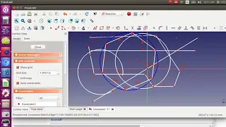
polygon,
there's
like
elliptical
things
so
good
for,
like
bolt
holes
very
useful.
Now
nothing
is
constrained
here.
So
you
can
move
things
around
still.
You
can
grab
that
you
can
grab
that
side
and
then
unconstraint
sketches.
You
could
do
anything
to
them
so
we're
gonna
move
around
on
you,
like
I,
grab
this
corner
here.
A
It's
gonna
move,
I
grab
this
side.
It's
gonna
move
the
entire
object,
I
grabbed.
At
one
point,
it
should
move
those
two
sides:
no
it
actually
in
a
square.
It
moves
everything,
but
if
I
do
it,
for
example,
a
polyline
just
observe
the
behavior,
because
the
sketcher
tool
is
very
useful
for
motion
analysis.
Like
say
you
got
a
backhoe
and
you
have
a
sketch
that
shows
okay,
an
articulation
for
a
backhoe.
A
You
can
do
things
observe
the
behavior
like,
for
example,
if
I
grab
that
point,
it
should
move
those
two
lines
attached
to
the
point,
because
nothing
is
constrained.
So
let's
check
that
see
that
that's
cool
that
actually
can
get
you
very
cool
motion
analysis
in
a
sense
like
let's
constrain
that
line,
for
example,
and
let's
constrain
that
line
by
saying
okay.
How
do
I
fix
that
so
I
selected
a
couple
of
things
there.
A
I,
take
that
point.
That
point
is
a
point
constraint
that
fixes
that
point:
okay,
for
example-
or
let's
say
no
I'm
gonna,
say
I-
want
to
fix
this
line,
and
that
point
you,
when
you
select
something
these
are
all
all
those
light
up
after
you
select
something
they're
not
gonna
appear
before.
So
you
have
to
kind
of
be
aware
where
you
are
so
for
awareness.
Where
are
we
now
we're
editing
a
sketch
and
we
got
into
constraining
of
a
sketch?
A
So,
let's
close
out
of
here,
so
you
know
where
you're
at
because
sometimes
it's
like
okay,
how
do
I
access
that?
It's
not
those
buttons
aren't
showing
up
or
I,
can't
edit
this
guy.
So
so,
first
of
all
do
the
sketch
edit,
the
sketch
you
want
to.
You
want
to
add
it
that
one
has
like
all
those
points
there.
This
is
our
second
one
here,
so
you're
selected
the
constraints.
A
The
behavior
is,
if
you
select
it,
the
constraints
all
appeared,
but
if
you
I
clicked
on
it,
they
disappeared
so
be
aware
of
that
they
just
disappeared
on
you're
like
well.
How
did
I
constrain
this
there's?
None
of
these
things?
Well,
you
have
to
select
something
you
want
to
constrain.
So
let's
take
this
one
line
and,
let's
I,
guess
and
probably
fix
those
two
points
select
two
or
more
vertices
from
the
sketch,
so
it
okay,
that's
what
it
told
me.
So,
okay
I
want
to
constrain.
Let's
just
constrain
that
point.
A
C
A
A
Okay,
let's
get
this
one
vertical
here,
I
just
got
that
one
selected
vertical
okay,
so
we've
got
guy
that
vertical.
Let's
make
this
one
horizontal,
so
this
is
horizontal,
so
it
straightens
that
out
now
what
happens
when
I
hit
that
point,
that
everything
is
still
moving
moving
around
so
how
do
I
fix,
for
example,
let's
say
I
want
to
fix
that
line,
equivalent
perpendicular
symmetric,
there's,
there's
a
bunch
of
different
ones.
A
A
A
A
So
this
might,
we
actually
might
have
run
into
a
crash
alrdy
because
I'm
not
able
to
move
things
right
now,
yeah,
okay,
so
keep
it
clean
like
once
you
get
enough
jumble
and
I
just
put
a
bunch
of
random
stuff.
Maybe
some
constraint
here,
that's
a
crash
alrdy.
So
let's,
let's
close
that,
let's
close
that
file.
A
So
the
key
is
that
you
just
play
with
a
whole
bunch
of
stuff,
observe
the
behavior
and
understand
that
you
can
draw
lines
and
then
constrain
them
in
various
ways.
So
to
give
you
a
you
know
like
a
simple
example:
if
people
want
to
follow
this,
no
cancel
that
so
I'm
gonna
just
cancel
out
of
the
air
close
without
saving.
We
don't
need
that.
It
gets
you
to
the
start.
Screen
start
a
new
one.
A
E
E
A
Let's
very
very
important
thing
here
is
measuring
less,
like
you
got
to
draw
an
object
that
you
know
the
dimensions
of
like,
for
example,
you've
got
some
of
the
3d
printer
pieces.
You
want
to
draw
it.
You
know
it
has
certain
sides.
So
let's,
let's
do
that
I'll
say:
let's
start
with
a
polyline
thing,
so
you
know
you
can
draw
freehand
like
this
or
you
can
draw
a
square,
but
freehand
everything
is
mobile
here
so
say
so
say
we
drew
it
freehand.
A
First
of
all
like
make
them
horizontal
that
one
I
already
kind
of
drew
horizontal,
make
that
one
vertical
make
this
one
vertical,
and
now
we
want
to
constraint
some
lenses.
Now
these
points.
Okay,
these
points
still
move,
so
you
can
constrain
them
by
selecting
a
length.
So
now
look
at
there's
also
there's
a
little
tab
here,
so
see,
there's
more
stuff
there.
So
you
want
to
move
it.
So
you
see
them
all.
You
kind
of
kind
of
drop,
drag
and
drop
things.
A
So
these
here,
okay,
so
the
lock
thing
was
well
and
that's
I
mean
I,
got
confused.
I
didn't
see
the
lock
thing.
I
wanted
to
lock
a
point
so
that
you
can
move
things
around
that
point.
So
let's
actually
show
you
that
for
the
backhoe
simulate
ctrl
z
to
delete
oh
I'm,
deleting
that
constraint
so
now
I
can
move
it
again.
It's
not
observe
that
behavior.
A
E
A
So
the
workflow
that
we
proposed
for
this
is
to
keep
things
as
simple
as
possible
because
of
the
bugginess,
but
also
to
keep
you'll,
keep
a
very
clear
workflow
based
on
parts.
So
as
soon
as
you,
what
I
like
to
do
is
is
use
the
workflow
where,
as
soon
as
you
have
something
like
say,
we
do
this
thing.
You
know
say
we
got
a
three-dimensional
shape,
save
it
as
a
part
in
a
part.
Library
and
I'll
show
this
and
then
there's
a
workflow
where
you
simply
merge.
A
It's
called
merge,
but
it's
under
file,
so
under
file,
there's
import/export,
merge
project
and
it's
not
appearing
because
I'm
in
edit
mode.
So
once
again,
this
is
awareness
where
you
are
before
you
do
anything
close
that
so
I
go
to
file
merge
project,
that
is
the
key
workflow
merge
means
you're
merging
another
free
cat
file,
not
not
exporting
or
importing.
C
A
Separate
but
the
way
to
keep
a
document
clean
and
get
away
from
troubles
like
because
just
for
your,
like
own
sanity
to
and
freak
out,
gets
confused
very
easy,
because
if
you
don't
have
things
constraint
properly,
the
the
thing
that
they
recommend
is
constrain.
Absolutely
everything.
So
once
you
have
a
drawing,
there's
zero
degrees
of
freedom
and
it'll
show
you
in
that
that
box.
It
shows
you
how
many
constraints
you
have
which
things
you
can
move,
which
means
a
degree
of
freedom,
so
go
ahead.
C
A
You
well
I
mean
you
can
open
that
thing.
You
merge
right
there
by
clicking
on
it
or
yes,
a
useful
thing
is,
if
you're
designing,
say
a
3d
printer
and
you
replaced
the
extruder.
That's
where
the
merge
functionality
is
very
useful
because
you
drew
up
say
you
have
the
CAD
from
elsewhere.
Just
merge
it
into
the
document.
That
is
key.
So
don't
try
to
do
like
okay,
I'm
gonna.
Do
this
one
master
big
file
for
the
3d
printer,
because
first
it's
gonna
get
heavy.
A
It's
gonna,
get
many
megabytes
depending
how
you
do
things
so
merging
individual
parts
is
a
very
much
recommended.
Workflow
and
I
do
would
say
it's
consistent
with
the
modular
design
principles.
Lets
you
keep
track
of
things.
If
you
want
to
borrow
that
part
elsewhere,
you
already
have
it
in
a
library.
So
please
do
that.
A
Export
and
import-
those
are
two
things
you
want
to
know
so:
STL
files
or
step
files,
for
example,
as
I
mentioned
mcmaster-carr,
has
step
files
for
everything
that
it
carries
mostly
mostly
everything
in
carry.
So
you
can
get
borrow
like
a
like
a
valve
3-way
valve
or
something
you're
using
that
in
your
tractor
or
something
borrowed
that
export
import.
It
import
it
as
a
step
file.
Let's
see
if
the
let's
go
to
McMaster
car,
just
to
show
you
that.
A
A
A
So
when
it
has
this
CAD
symbol
there,
it
says
it
it.
You
can
find
that
as
a
CAD
model,
you
kind
of
have
to
know
how
to
navigate
you.
So,
for
example,
go
to
this
specific
quarter
by
quarter
inch
valve
for
$8.00,
and
then
it
goes
into
product
deked
detail
with
a
CAD
symbol
and
there
it's
gonna,
be
it's
gonna
have
the
CAD
drawing
so,
for
example,
you
can
take
this
CAD
drawing
you
can
actually
import
images
into
free
CAD.
So,
for
example,
you
can
put
that
in
your
background
actually
draw
over
this.
A
In
freecad,
let's
not
get
into
that,
but
here
what
I
wanted
to
show
is
that
okay,
3d
step-step
file
is
what
you
want.
Free
cat
imports
it
so
the
different
choices
you
have.
Our
D
draw:
iges
PDF,
the
SAT
SolidWorks
SolidWorks
step.
So
SolidWorks
is
a
proprietary
format.
D
sad
I,
don't
know
what
that
is.
Pdf
is
gonna,
be
probably
this
PDF
drawing
iges
is
gonna,
be
three
3d
you
drawing
out
on
what
that
is,
but
step
is
a
three
dimensional
one
step.
A
A
That
do
it
there.
No
so
so,
then
you
can
import
it
into
free
CAD,
and
this
is
for
various
sources,
as
various
online
repositories
like
grab.
Cad
is
a
big
repository
of
open
various
designs
on
the
different
licenses,
but
yeah
any
decent
manufacturer
should
have
a
full
CAD
file.
If
they
don't,
you
should
call
them
up
and
say:
hey
where's,
your
CAD
file.
Some
will
give
it
to
you.
A
Others
who
are
more
proprietary
will
not
like
you,
probably
we'd,
love
to
have
a
full
engine
file
from
Briggs
&
Stratton,
for
example,
for
the
power
cubes,
but
they
probably
will
not
give
it
to
you,
because
if
it's
a
full
file
it
allows
you
to
replicate
it.
So
it's
a
powerful
thing.
A
fully
detailed
CAD
file
is
very
valuable
because
it
took
that
design
digital,
which
means
that
it's
infinitely
replicable,
if
you
have
the
means
to
replicate
it,
but
here
mcmaster-carr
has
all
these.
These
are
stock
of
the
shelf
industrial
parts.
A
Import
select
a
file
so
that
this
is
the
one
I
just
downloaded
here.
This
ball
valve
so
open
that
and
it
should
get
you
in
there
and
it's
probably
got
the
threads
in
there,
which
you're,
probably
gonna,
take
a
lot
of
memory.
I
mean
it's
taking
a
little
bit
to
import
it,
so
that
thing
is
probably
sizable
like
probably
a
megabyte
or
more
I
just
want
to
get
the
info
on
it.
Just
to
show
you,
because
you
have
to
pay
attention
to
memory
size
like
okay,
so
there's
my
valve
die
just
imported.
A
Isn't
that
great
and
that's
it
so
it's
fully!
You
know
you
can
now
3d
print
it.
For
example,
you
can
go
to
file
export
and
you
can
do
STL
file
as
a
selection.
So
that's
how
you
would
you
select
it
export
it
as
an
STL
and
that's
ready
for
3d
printing,
so
he
could
do
like
a
if
you
want
a
3d
model,
your
power
cube.
Well,
we
could
do
like
a
little
scale
model
of
this
and
print
it
out
and
use
it
as
an
actual
model.
A
You
can
even
print
the
threads
and
probably
even
thread
in
stuff.
Like
that,
so
it's
very
powerful.
It's
a
full
full
reverse
engineering
workflow,
so
I
won't
go
into
that,
but
I
just
want
to
show
the
memory
size
of
that
properties
and
that
thing
is
yeah
exactly
one
megabyte.
So
that
means,
if
you've
got
a
few
of
these
in
there
the
file
is
gonna.
Get
pretty
heavy
really
fast,
like
limit.
That
I
would
recommend
is
like
10,
20
30,
maybe
30
megabytes.
But
after
that
you,
you
know
it
starts
to
slow
down
quite
a
bit.
A
A
We
would
do
a
file
simplification
procedure
actually,
so
we
would
just
take
this
and
just
draw
it
in
freecad
like
so
so
what
we
could
do,
for
example,
you
know
you
take
it
to
a
do
proper
view
like
from
this
head-on
part
right,
so
I
would
just
reverse
engineering
and
freak
odd,
I
would
say:
okay,
let's
draw
it
in
freak
out
it
because
I'm
freaked
out
native,
for
example,
there's
probably
threads
in
there.
If
you
look
in
there
there's
threads,
they
take
a
lot
of
memory
strip,
the
threads.
So
what
I
would
do
here.
A
You
can
basically
draw
it
using
that
as
a
template,
so
you
go
into
that
plane,
whichever
that
plane
was
and
then
so
that's
the
XY
plane
actually
I
lost
myself
where
am
I,
so
I
want
to
go
to
that.
Sketch
was
in
that
that
direction.
I
think
I
need,
like
I,
think
I
probably
need
an
XY
plane,
so
sketch
new
sketch
XY,
that's
right.
It
got
positioned
on
the
on
the
XY
plane,
so
I
would
go
here
and
I
just
take
my
you
know.
A
To
make
it
look
nice
out,
I'll
just
go
well,
I
mean
we.
The
polygon
is
easy
to
do
so.
I
would
start
at
the
center.
You
kind
of
have
to
know
how
far
you
went.
So
you
I'm
gonna
go
to
that
corner
about
okay
there.
So
close
it
and
I'm
gonna
make
this.
This
thing
disappear
by
hitting
hitting
a
button.
So
the
cool
thing
about
a
basic
workflow
freakout
is
you
can
hide
and
unhide
things
by
clicking
on
something
and
pressing
spacebar
you
can
literally
so
so
you
know
you've
got
this
valve
here.
A
You
can
select
part
by
part
to
expose
the
build
structure
of
an
aviary
complex
thing.
That's
one
way
to
do.
Instructionals
is
when
you
just
hide
hide
part
by
part
like,
for
example,
with
a
brick
press.
We
did
that
to
do
a
fabrication
procedure
on
it.
We
would
just
take,
you
know,
put
it
in
the
first
part
or
like
take
the
whole
brick
press
take
off
one
part,
the
next
part
next
one
until
your
to
like
one
part
and
then
reverse
the
order
of
that
and
that's
a
build
procedure
right.
A
Okay,
so
I
just
want
to
show
like
so
that's
one
megabyte,
and
so
we're
talking
about
memory
issues
and
that's
part
of
the
memory
issues
is
you're
in
a
design,
Jam
environment.
You
can't
be
waiting
around
two
people
for
people
to
get
frustrated.
You
want
it
to
be
snappy
and
clear.
So
in
this
case,
I
would
definitely
turn
this
from
one
megabyte
to
like
10k
5k.
A
So,
just
to
show
you
that,
as
an
example,
so
the
of
the
sketcher
workbench
I'm
gonna
go
back
to
my
sketch
here
that
I
did
I'm
gonna
hide
my
hide
my
Val,
so
this
sketch.
So
let's
talk
about
the
extrusion,
so
that's
that's
sketch
number
two
right,
let's
start
getting
into
the
extrusions,
so
the
Edit
ability
of
those
dimensions.
Yes,
you
should
be
able
to
click
on
a
dimension
like
in
our
former
sketch,
wherever
that
was
okay,
like
this
five
inches
double-click
on
it,
make
it
eight
inches.
A
That's
all
editable
and
that's
useful
because
you
can
edit
all
these
kinds
of
things.
I
can
still
move
this
because
it's
not
so
constrained
to
constrain
it
I
would
go.
The
lock
thing
select
one
vertex
from
the
sketch
other
than
the
origin.
So
so
the
lock
works
on
vertices.
So
take
that
sketch
lock
it
okay,
so
you
just
locked
it
now.
You
probably
can't
move
this
anymore,
but
can
you
move
these
points?
Yeah?
You
can
still
move
these
points
because
that
side
isn't
locked.
Just
that.
A
One
point
is
locked
so,
but
I
like
to
like
when,
when
you
get
into
a
complex
design,
you
know
it's
right,
I,
just
erase
everything
just
to
keep
the
simplicity
in
that
design
and
also
takes
less
memory.
So
like
really
strip
it
down
because
say
because
you
don't
you
don't
delete
it,
you
save
the
source
file,
save
save
the
source.
You've
got
the
full
file
with
all
the
dimensions.
If
you
want
to
now
mess
with
it,
don't
get
confused.
If
you
know
it's
right,
just
might
as
well
strip
all
the
dimensions.
A
If
you
want
to
modify
something
or
if
you
want
to,
if
you
want
to
modify
a
Sai
parametric
ly,
add
that
dimension
and
then
he
can
double
click
and
change
that
dimension,
so
he
can
add
all
the
dimensions
back
to
it
anyway,
I
like
to
strip
things
too
I
like
to
keep
things
as
simple
as
possible,
no
fluff
in
a
design,
so
here
I,
would
go
into
all
my
constraints.
Like
say
somebody
did
a
complex
design,
so
I'm
talking
about
here
everything
from
the
point
of
collaborative
development.
You
just
picked
up
somebody's
file.
A
A
A
So
that's
that's
flexible!
Now
everything
is
back
to
unconstrained.
You
can
modify
it
even
the
lines.
Split!
Oh
yeah
there.
You
know
splitting
it
apart
completely.
Ok,
but
let's
go
back
to
our
so
once
again
like
ok,
where
are
you
here
well
scroll
up
to
close
it?
So
you
can
make
sure
you
know
where
you
are.
It
goes
back
to
the
sketch
there's
a
Model
View
and
a
tasks
view
so
make
sure
you're
in
the
Model
View.
That's
another
item
you
have
to
remember.
That's
the
tree
view.
It's
got
all
the
parts
in
here.
A
Ok,
so
I
want
to
reverse
engineer
that
valve
I
just
drew
over
the
the
one
face
and
that's
sketch
number
two
there
so
close
out
of
there
go
into
then
part
design,
so
the
workbench
selection
is
that
button
up
there.
You
can
work
in
various
different
work
benches,
which
will
have
different
tools
on
top
you're,
still
working
with
the
identical
same
design.
It
just
allows
you
maybe
to
do
different
things
upon
that
design,
so
in
a
part,
design
workbench.
A
It
now
gave
you
all
these
other
tools
of
which
the
two
relevant
ones
are
this
one
which
is
pad
a
selected
sketch
and
the
second
one,
which
is
called
create
a
pocket
within
the
elected
sketch.
So
let's
extrude,
so
this
is
extrusion
you're
making
something
three-dimensional.
So
now,
let's
take
our
primitive
of
this
valve.
A
So
once
again,
so
do
this
we
close
out
of
there
but
select
it
don't
double-click
it
but
select
it
and
double
click.
You're
editing
it.
You
cannot
do
these
operations
upon
things
that
are
being
edited
and
probably
those
symbols
should
disappear.
They
got
blanked
out.
You
got
back
into
sketcher,
which
gets
you
all
the
constraints
and
everything
so
close
out
of
the
edit
mode,
but
select
it
so
you're
selecting
things
here
select
sketch
now:
let's
Pat
it.
A
Ok,
it
started
a
pad.
Let's
make
it
5
inches
long
for
length.
Okay,
there
you
go
so
you
just
created
a
three-dimensional
thing.
Well,
I
could
keep
working
it.
I
can
do
the
cylindrical
part
and
so
forth.
So
let's
do
the
cylindrical
part.
So
this
is
the
power
of
freaked-out.
You
can
take
any
side
now
and
you
can
draw
more
things
on
it.
More
features
on
it
say
you
want
to
put
a
handle
on.
It
say
this
is
a
representation
of
your
valve
and
that
thing,
let's
hide,
hide
the
other
thing
yeah.
A
So
that
thing
appeared
from
mcmaster-carr
and
multiple
pieces
like
that
handle
opened
up
as
multiple
pieces.
Sometimes
it
gets
you
like
one
one
chunk.
Sometimes
it
gets
you
multiple
pieces
depends
who
did
the
file
how
they
exported
it?
Ok,
so
we've
got
our
our
thing,
so
I'm
I
selected
that
face
and.
A
A
A
That
thing
appeared,
which
is
to
put
a
new
new
sketch,
and
you
can
put
that
new
sketch
anywhere.
There's
this
other
one.
That's
that's
map
a
sketch
to
a
face.
We
don't
need
to
do
that.
Just
use
use
this
one,
that's
getting
a
little
a
little
more
advanced
just
use
the
face.
That's
still
too,
you
can
still
put
a
okay.
A
Draw
shape,
you
got
a
shape,
select
it
with
entry
view,
don't
double
click
then
go
into
part
design
and
click
the
pad
tool.
Part
design
workbench
is
the
key,
so
that's
got
it
there.
Did
it
extrude
there,
so
this
is.
This
is
easy,
so
click
on
any
face.
It
gets
you
the
the
sketch
item,
so
it
automatically
takes
you
to
that
face
when
you
clicked
on
it.
So
we
that
looks
pretty
long.
Why
is
it
that
long?
A
Okay,
no
that's
good!
So
so!
Okay!
Now
it
asks
you
what
plane,
if
you
don't
specify
a
plane,
it
will
ask
you
what
plane
do
you
want
to
put
it
to
now
here?
It
only
has
three
planes
in
the
actual
CAD
it
has
more
than
three
planes.
Any
face
is
a
plane.
So
if
you
select
it
like
I
did
and
it
turned
green
there.
You
can
see
that
I'm
gonna
put
a
sketch
on
it,
so
it
aligns
you
right
to
it,
get
you
right
on
it
and
now,
let's
poke
a
little
hole
through
that.
A
So
let's
do
our
say.
We
need
like
put
a
big
bolt
through
that
through
this
shaft
thing.
Okay,
close
it
just
did
it
I
did
this
new
sketch
to
sketch,
for
which
is
selected.
So
let's
go
back
to
part
design
now
we're
gonna
do
the
path
the
the
pocket
creates
a
pocket,
so
I'm
gonna
click
that
that's
it,
and
then
it
tells
you
what
kind
of
length
like
if
you
want
it
to
be
all
the
way
through
it
just
got
me
here.
It
got
me
a
little
bit.
I
want
to
be
all
the
way
through.
A
So
this
is
cool
stuff,
like
you
can
start
doing
all
kinds
of
things
you
can
draw
features
anywhere.
You
can
draw
features
on
internal
parts
like
if
I,
if
I
do
another,
say
a
square.
So
let's
do
this
thing
well,
actually,
let's
do
a
bit
bit
holder,
so
the
big
holder
was
essentially
this
with
a
smaller
thing
on
the
inside.
So
let's
draw
on
that
face.
Don't
select
the
whole
object.
That's
two
clicks.
First
click
selects
that
face
which
is
green
now,
I'm
gonna
put
a
actually
this
part
design
has
that
same
tool
there.
A
A
And
hardly
see
it
there,
so
if
you
can
hardly
see
it,
you
want
to,
you
can
do
things
like
hide
the
thing
you
just
drew,
but
sometimes
the
color
scheme
might
not
be
good.
So
once
again
in
the
tree
view
just
hit
the
space
button.
Now
we
want
to
make
sure
that
this
is
if
this
is
gonna
fit
a
quarter
inch
bit.
Let's
make
this
quarter
inch
size,
but
let's
do
maybe
things
like
in
the
constraints.
A
A
A
0.25
inch,
so
we
got
that
there
you
go
so
that
that
would
actually
hold
the
bit
now
close
it
so
now,
I
want
to
pocket
so
I
know,
that's
sketch
number
five
I
want
to
pocket
what
I
had
before.
So,
let's
make
the
other
thing
up
here.
Let's
cut
this
whole
out,
so
I'm
so
I
want
to
just
select
sketch
five.
It
appears
there
it's
off
offset
a
little
bit.
We
can
go
to
sketcher
and
move
it,
but
I
want
a
pocket.
So
I
got
to
go
back
to
part
design.
Do
the
pocket
operation?
A
It's
gonna,
get
you
a
little
pocket,
but
you
want
to
go
all
the
way
through,
so
it
will
be
in
order
to
make
it
go
all
the
way
through
select
the
length
to
be
like
ten
inches,
whatever
it
doesn't
matter,
so
it
poked
it
all
the
way
through
and
it's
poke
poke
through
that
hole.
So
you
see
you
get
very
complex
geometries
now
now
the
other
thing
I
want
to
show
is
orthographic
view
versus
perspective
view.
A
Perspective
is
looks,
looks
better,
but
it's
harder
to
it's
actually
harder
to
get
things
like
on
one
face,
because
if
you
say
you
look
at
it
from
a
particular
angle,
it
doesn't
look
flat
to
you
like
from
the
other
orthographic
view.
It
looks
like
a
square
thing
now,
for
example
like
look
at
that
thing,
but
this
is
perspective
view.
If
you
go
into
orthographic
view,
that's
gonna,
look
like
a
square,
so
it's
easier
to
kind
of
like
analyze
it
or
hit
a
corner,
or
something
like
that,
so
that's
kind
of
like
the
basic
workbook.
A
A
My
screen
is
kind
of
small,
so
I
don't
have
a
lot
of
space
here,
but
that
was
the
last
sketch
I.
Did
this
sketch
number
six?
So
let's
edit
it
actually
but
I
want
to
hide
this
other
thing.
Cuz
I
can't
see
things
so
those
points
are
not
aligned
like
you
can't
pad
this
thing
because
it's
not
closed
so
one
way
to
do
it.
Select
the
two
points
make
him
make
him
constrained
so
hit
the
point.
A
A
So
we
can
close
that
select
that
sketch
number
six
and
make
a
make
a
pat
on
it,
make
it
like
one
inch.
So
how
does
my
thing
look
now?
You
know
we
have
just
created
that
on
the
side,
so
you
can
now.
As
you
see,
you
can
start
doing
all
kinds
of
crazy
stuff.
If
you
have
the
ability
to
draw
any
shape
within
a
sketcher,
you
can
draw
just
about
anything.
A
You
can
draw
like
a
floor
plan
of
a
house
that
you
can
then
extrude
like
with
all
the
rooms
or
whatever
and
do
a
lot
of
things,
but
it
is
kind
of
its
limited
in
the
sense
that
you're
only
going
up
like
one
direction,
but
you
can
go
in
different
directions
depending
on
as
long
as
you
have
a
face.
If
you
want
to
do
more
irregular
things,
only
other
thing,
I
can
say
that's
quite
useful
and
very
easy,
as
in
the
part
workbench,
you
have
primitive
shapes
like
a
cone,
a
sphere.
A
So
you
know
like
let's
draw
a
cone
where
to
put
that
cone.
I
put
it
like
a
small
cone
right
in
there
that
cone
there
you've
got
some
basic
things
that
are
just
one
click,
but
there's
still
parametric.
So
you
can
change
the
sizes
of
all
the
sides
and
everything
like
that,
but
that's
the
basic
workflow
that
I
want
to
show
you
and
with
this
like,
for
example,
the.
If
you
take
a
look
at
the
3d
printed
pieces
for
the
axis,
you
can
do
this
with
this
and
you
can
try
it
yourself.
A
What
would
you
do
there
start
with
a
square?
You
know
you've
got
the
bolt
holes
for
the
hole,
so
that
would
be
holes.
You
know
you've
got
the
nut
catchers
like
they're
hexagonal,
so
you
can
catch
we're
actually
using
round
screws,
but
if,
if
we
used
hexagonal
screws,
we
could
do
that
our
folds
are
hexagonal
there.
So
you
could
do
that.
You
can
do
all
the
magnet
holes
just
by
little
holes
where
the
magnets
are
so
take
the
carriage
piece.
Well,
how
do
you
do
the
holders
for
the
bearings
in
there?
B
A
You
do
you
do
it.
It
depends
on
what
you're
doing
like.
If
you
want
something-
and
it
also
depends
on
your
printer,
if
your
printer
is
sloppy
and
it
might
print
a
little
bit
in
if
you
draw
a
quarter-inch
ball
tall,
you
might
not
fit
a
quarter-inch
bolt
in
there,
so
you
might
want
to
do
a
quarter-inch
plus
like
1/16
or
something.
So
you
have
to
consider
how
well
your
printer
is
printing.
If
your
printer
is
printing
with
the
like
a
one
point,
four
millimeter
tool
head
extruder,
then
that
discrepancy
might
be
might
be
large.
A
We
can
say:
okay.
This
is
exactly
what
we
get
when
we
do
that,
that's
something
that's
worth
documenting
for
a
production
engineering.
You
want
to
know
exactly
what
the
results
we
have
like.
For
example,
we
had
issues
with
a
one
of
the
bolt
holes
where
the
square
square
nuts
we're
rotating
within
a
square
hole.
That
means
somehow
the
hole
got
printed
a
little
too
large.
It
may
be
that
it's
possible
that,
because
I
printed
it
so
fast,
it
got
a
little
bit
inaccurate
because
of
course,
if
you
print
slower
you're
gonna
be
more
accurate.
A
If
you're,
printing,
you
a
two-by-four,
you
definitely
want
to
print
on
your
the
speed
because
you
got
a
lot
of
material
to
print
and
the
dimensions
aren't
critical
that
you're
one
millimeter
off.
So
it
depends
where
you
are
and
that's
that's
the
thing
that
makes
you
can
say,
3d
printing
a
little
bit
challenging
because
a
lot
of
times
you
can't
just
say
oh
I'm,
just
gonna
download
this
file,
it's
gonna
work.
A
You
have
to
understand
what
your
printer
can
do
like,
for
example,
if
you
have
a
fan,
you
can
bridge
overhangs,
so
you
have
one
one
thing:
you're
printing
two
sticks,
you're
printing.
You
want
to
bridge
over
then
like
to
make
a
table.
You
know
how
far
can
you
go?
What
is
that
overhang
that
you
can
do
in
theory?
If
you
go
super
super
slow
and
you
got
the
fan
blasting.
It's
not
a
reason
why
you
can't
extend
that
till
as
much
as
that.
Back
to
your
mechanical
strength.
That
is
solidifying
as
it's
going.
B
A
Yeah
yeah
so
just
like,
when
you
do
the
3d
print
printed
with
a
welder
thing,
I
mean
you
can
once
the
weld
solidifies
it's
you
can
start
like
that.
Then
you
can
print
vertically
like
downwards,
against
gravity,
of
course,
because
you're
attaching
it
to
something.
That's
already
frozen
things
like
that.
So
you
have
to
understand
some
of
the
physical
features
so
so
and
that's
the
kind
of
stuff
we
record
and
document
it's
what
makes
the
hardware
much
more
complicated
than
software,
because
the
compiler
includes
gravity.
You
know
gravity
like
gee
like.
A
Are
you
on
the
surface
of
the
Moon
or
are
you
on
earth?
You're
gonna
have
different
conditions.
That
would
be
your
fork.
This
is
our
fork
for
lunar
printing.
You
know
it's
literally
like
that,
and
this
is
also
why
I
say
every
build
has
going
to
have
different
conditions
that
you
have
to
document
and
why
that
would
take
a
lot
of
memory
because
you
have
to
package
all
that
up
into
one
one
power
ball.
A
Yes,
it
does
so,
let's
talk
about
that
one,
because
when
we
do
3d
printing,
we
work
with
meshes
which
are
STL
files
and
STL
files
aren't
handled
well
within
freecad
like
because
they're
made
of
multiple
surfaces,
you
can't
just
like
modify
it
easily.
So,
typically,
what
you
do
is
you
convert
it
to
a
solid
first
there's
some
STL
files
that
you
can
do
that
readily
and
I
explained
it
in
one
of
my
two
five-minute
videos:
how
to
go
through
that
process.
So
I've
got
the
two
5-minute
freecad
101
videos
you
select
that
object.
A
Then
you
basically
turn
it
into
a
solid
through
a
few
steps
in
the
part
workbench.
But
without
that,
for
example,
you
cannot
do
these
operations
like
select
the
face
and
poke
a
hole
through
it.
You're
gonna
have
to
convert
that
mesh
file
into
a
solid
file
first,
because
the
mesh,
the
way
it
appears
in
free
CAD,
is
essentially
I
think
a
lot
of
times
it's
empty
on
the
inside
and
it's
just
got
a
bunch
of
surfaces.
So
it's
not
a
solid,
it's
it's
a
bunch
of
polygons
and
it's
treated
differently.
A
So
the
way
to
do
that
is,
you
can
operate
it
within.
As
I
mentioned
blocks
CAD
you
can
definitely
modify
it
in
block
scale.
You
can
poke
holes
and
things
do
the
boolean
operations
boolean,
meaning
like
subtraction
addition
intersection
blocks
cat.
Does
that
well
and
free
CAD?
The
requirement
is
that
you
convert
it
to
a
solid
first
before
you
do
that
kind
of
stuff,
but
not
all
you
can
do.
You
cannot
do
the
the
padding
functions,
but
you
can
do
boolean
operations
within
freecad
in
the
Park
workbench.
If
you
have
two
shapes
within.
A
Words
that
part
design-
no
it's
in
part,
but
if
you
have
so
say
you
drew
up
a
couple
of
things:
I
just
clicked
on
them.
They
appeared
like
at
the
origin
there
they're,
probably
superimposed
against
one.
Another
yeah
is
that
ball
that
I
just
drew
here.
Let's
select
that
yeah
that
ball
well
yeah
here
the
boolean
operations
start
appearing,
so
you
can
join
things
like
this.
A
One
is
I,
think
addition,
but
if
you,
if
in
a
tree
view
now
you
got
so
say
you
got
the
sphere
and
the
cone
that
you
click
shift
to
select
both
of
them
and
all
your
boolean
operations
now
have
appeared.
So
you
can
take,
for
example,
an
intersection
of
these
right
here
now,
I'm,
not
sure
what
happened
there,
but
something
happened.
Oh
yeah!
What
happened
there
was
I
ate
the
top
of
the
pyramid
with
what
the
ball
intersected
with
it.
So
you
do
boolean
operations
you
can
do
like.
A
If
you
have
a
cube,
you
can,
like
you
know,
cut
that
off
with
a
boolean
operation
by
doing
a
subtract
so
that
you
can
still
do
it's
more
complicated
with
in
freaked
out,
because
you
have
to
select
the
proper
thing
and
once
you
select
the
two
things
you
have
to
select
make
sure
you
know
which
operation
out
of
these
it's
easier
in
blocks
cad
to
do
that.
But
that
is
a
common
workflow
say
we
got
the
extruder.
So,
for
example,
extruder
we
got
STL
files
from
the
Pusa
printer.
They
did
not
have
open-source
cad.
A
They
do
not
have
SDL's
sorry
step
files.
Most
people
do
not
use
free
CAD,
except
for
lulzbot
like
which
is
my
favorite
company.
That's
that's
the
3d
printing
company.
It's
a
fully
open
source
company
Lowe's
about
they
provide
free,
CAD
files
for
everything,
so
the
Lowe's
about
printers
any
parts
that
are
on
that
printer
are
in
full
CAD
within
freaking
because
they
care
about
it.
Just
like
we
do.
They
understand
that
if
you
have
free
CAD
now
anybody
can
do
it
for
the
most
of
the
other,
guys
like,
for
example,
for
the
extruder.
A
We
don't
have
that
in
free,
CAD
or
step
file.
We
have
only
STL's,
which
means
we
cannot
do
the
various
operation.
We
can
only
do
like
the
boolean
's
here,
but
we
can
so
the
way
I
did
that
screw
hole
cuz
that
screw
hole
that
little
tiny
screw
hole
for
the
back
mounting
plate,
I
put
that
in
there
and
that's
simply
subtracting
that
hexagon
from
that
shape
and
that
did
work
within
the
boolean
operations
here.
So
that
is
a
common
workflow.
A
So,
with
that
said,
like
any
questions
on
that,
where
we
are
on
I
mean
that
basic
workflow
you
can,
you
can
definitely
design
the
carriage
pieces.
You'd
say:
okay,
how
do
I
do
that
a
cylinder
in
there?
Well,
how
do
you
do
that?
Well,
if
you
look
at
the
short
side,
you
can
draw
on
us
face
of
that
a
circle
and
the
circle
will
eat
all
the
way
through
to
make
a
partial
cylinder.
So
you
have
to
think
kind
of
think
about.
A
Well,
how
did
what
are
the
primitives
inside
there
and
how
do
I
logic
that
out
to
make
it
happen
using
simple
operations
and
it's
kind
of
like
creative
exercise,
but
I
mean
you
know
elementary
school
children
can
do
that
blocks.
Cat
is
designed
for
people
like
down
to
like
elementary
and
stuff
question.
A
Yeah
yeah,
you
can
do
just
about
all
of
them
and
it
depends
where
you
are
so
you
have
to
play
with
it,
but
but
in
a
hexagon.
What
do
I
need
to
know?
I
need
to
know
that
it's
gonna
fit
my
bit,
and
you
know
the
sides
if
it's
to
design
constraints
there,
where
I
want
the
sides
to
be
parallel
for
a
small
hole
in
a
big
hole,
so
I
I
did
that.
So
what
were
all
the
constraints?
A
One,
the
dimension
of
it?
So
just
the
dimension
across
the
two
points
before
that
I
already
drew
the
hexagon
and
a
hexagon
had
all
equal
angles
and
everything.
So
that's
already
there
and
the
only
other
thing
I
need
to
Center
it.
So
that's
gonna
be
a
constraint
where
the
center
of
the
my
hexagon
is
the
same
as
the
other
Center
and
what
else
the
angle
I
did
by
making
the
sides
parallel.
I'd
made
the
side
vertical
so
three
constraints.
A
Essentially,
if
you
don't
need
to
do
anymore,
don't
do
it,
however,
sometimes
there's
and
I'm
not
sure,
because
I
typically
erase
my
constraints,
don't
have
enough
experience
with
it,
but
they
say
that
unless
you've
got
every
single
thing
constraints,
if,
if
there's
degrees
of
freedom-
and
let's
look
at
look
at
that-
so
say
we
take
a
look
at
the
model
and
take
this
sketch.
It
has.
A
This
thing
called
like
I,
think
solver
messages
here,
I
think
it
says
there
I
read
that
it
might
say
like
fully
constrained
or
there's
there's
missing
constraints
and
I
think
the
way
the
free
CAD
works
is
when
our
missing
constraints,
it
can
crash
easier.
But
then
again
in
my
sketches
like
if
you
do
a
simple
sketchy
extruded
as
long
as
you
do
the
merge
workflow,
where
you're
putting
one
file
into
the
next,
the
merge,
never
crashes.
If
you
get
like
a
one
single
file,
that's
got
all
these
parts
in
it.
A
It
tends
to
crash
more
so
you
want
to
separate
it,
but
do
minimal
constraints
whenever
possible
and
if
you
really
needed-
and
it's
crashing
on
you
just
get
rid
of
all
the
degrees
of
freedom
and
constrain
it,
because
sometimes,
for
example,
one
thing
where
it
does
come
in
okay,
you
did
a
perfect,
complicated
shape.
You
want
to
Pat
it
and
says:
error.
A
It'll
actually
tell
you
like
not
point.
Maybe
it
tells
you
points.
Aren't
it's
not
a
closed
shape,
but
it
might
not
so
one
just
the
other
day,
I
was
doing
stuff
and
stuck
okay,
wouldn't
wouldn't
wouldn't
extrude
out
I'm
like
what's
going
on.
All
the
points
are
visually
everything
looked
okay,
but
it's
I
think
what
was
happening.
There
was
one
point
wasn't
close
done
to
the
last
one,
so
that
failed.
A
So
that's
where
you
want
to
have
okay
make
sure
everything
is
like,
but
two
last
points
are
constrained:
definitely
because
that
could
either
just
not
work
or
maybe
crash,
or
something
like
that.
So
in
theory
setting
all
the
constraints
is
good
and
practice.
I
mean
if
you've
got
a
complicated
shape
like
the
hexagon
or
something
that
you
drew
up.
I
mean
a
free-form
shape
that
you
drew
up
to
constrain.
Everything
is
a
lot
of
work.
A
Why
do
it
if
you
don't
have
to
so
I
would
say
for
practical
purposes,
avoid
it
if
you
can
and
if
we're
doing
reverse
engineering
work
like
say
that
Valve
and
we
want
to
draw
that,
handle
we're
just
tracing
over
it
by
looking
at
the
imported
image
and
we're
just
redrawing
it.
Yeah
you're
gonna
have
a
bunch
of
lines.
You
can
do
freehand,
but
you
don't
want
to
constrain
all
of
them.
No
need
to
so
takes
a
lot
of
work.
So.
A
A
It's
at
that
level
like
it's
just
for
safety,
it
does
do
autosave,
I
I
think
you
might
be
able
to
set
those
settings
I'm
not
sure,
but
my
workflow
is
just
ctrl
s
every
time,
I've
added
something
that's
worth
keeping
which
I
mean
if
you've
got
a
complex
design.
You
might
be
thinking
about
it
for
a
long
time.
So,
typically
it's
not
an
issue.
It's
a
okay!
You
figure
it
out.
You
draw
just
click.
Control,
save
right!
A
C
A
Not
so
much
there's
a
thing
called
macros
in
here,
you
can
actually
record
a
sequence
of
steps
to
do
something.
Yeah,
don't
really
want
to
get
into
all
that,
but
you've
got
macros
and
ability
to
write
little
programs
and
make
new
work
benches
here,
like
the
workbench
that
we
have
here
like
part
design,
sketcher
we're
working
on
one
it's
for
the
3d
printer
which
what
it
does
is
you
click
on
that
and
the
icons
that
appear
here.
A
That's
that
will
be
in
our
next
release
of
the
OSC
Linux,
but
we
have
a
thing
where
you
click
on
3d
printer
workbench
and
has
the
icons
the
frame
the
axes
and
you
simply
click
on
that.
It'll
drop
that
into
the
picture.
So
you
can
do
that
very
easily.
So
bhakti
was
working
a
little
bit
on
that.
We've
got
some
people
on
a
team
that
have
begun
that
process.
We
actually
did
a
complete
PVC
work
bench.
You
can
generate
any
kind
of
PVC
pipe
or
whatever
corner
like
T's
like
crosses
elbows.
A
That's
actually
very
useful
I
mean
nobody
has
that
out
there.
So
we
did
it
because
we
use
a
lot
of
PVC
and
we
want
to
have
any
kind
of
variation
we
need
so
that
that
workbench
exists
and
that's
something
in
programs.
So
that's
that
shows
you
how
useful
packages
like
freak
out
to
be.
You
can
put
a
design
library
for
anything
any
single
thing.
As
long
as
you
have
the
the
parts
that
are
admissible
parts,
you
provide
also
a
design
guide
that
tells
you
okay,
this
is
how
things
work
and
how
they
go
together.
A
Any
person
then,
can
start
designing
real,
meaningful
objects
and
that's
very
powerful,
so
that's
a
capacity
that
we
have
and
it's
not
not
happening
because
it's
a
capacity
that
exists,
but
we
need
to
generate
those
part,
libraries
and
resources
that
make
it
practical
and
first
is
like
learning,
free,
CAD
making.
You
know
free
cuts,
improving
constantly
it's
getting
better
and
easier,
and
so
there's
a
lot
of
power
to
what
we
can
produce
for
the
general
public
on
that
front
and
reinvent
local
production.
B
A
A
Other
people
have
done
things
like,
for
example,
there's
a
shipbuilding
workbench,
some
shipbuilding
guy
decided
to
put
in
tools
for
building
holes,
ship
holes
and
stuff.
So
so
you
can
do
it
for
anything
like
car
building,
workbench.
You
know
as
long
as
like
a
lot
of
it
is
you
don't
know
which
parts
to
use?
But
if
someone
already
told
you
what's
admissible,
when
you
have
that,
then
you
say:
okay,
we
know
that's
engineered
to
work.
We
can
now
use
use
that
as
a
construction
set.
A
So
that's
how
you
democratize
production,
because
right
now,
all
that
knowledge,
all
your
special
engineers
and
professionals
have
that
and
not
a
lot
of
them.
Think
about
sharing
that
to
the
public.
So
that's
a
big
gap
in
society,
that's
there,
but
we
can
definitely
address
that
to
make
life
easy
for
everybody.
So,
like
you
know
like
with
the
3d
printed
fittings,
there's
actually
a
group
in
the
Solomon,
Islands
or
Australia
that
they're
3d
printing
fittings
are
high-pressure
fittings
hundred
to
hundred
psi.
A
You
know
that
kind
of
stuff
where
they
did
it,
because
they
don't
have
easy
access
to
do
fittings
in
the
Solomon
Islands.
But
that's
the
kind
of
stuff
you
can
be
talking
about.
You
know
save
our
trip
to
the
to
the
store
when
we're
in
the
middle
of
building
the
CD
qahal
need
plumbing
fittings.
We
missed
one
part
just
printed
right
there.
What
you
do
want
to
have
a
good
printer,
fast
printer.
You
want
to
have
experience
with
it.
You
don't
want
to
just
say:
oh,
like
first
of
all,
you
got
to
have
the
file.
A
You
gotta
know
how
to
print
it,
what
you
need
all
of
that.
So
so
you
got
a
you
got
to
be
aware
of
that,
but
that
kind
of
awareness
is
readily
achievable
so
that
when
we
have
our
crazy
builds
you
we
can
be
just
having
running
you
know
we
can
have
a
wall
of
our
printers,
not
producing
all
the
aquaponics
parts,
all
the
plumbing,
as
the
other
team
is
doing
other
stuff,
and
that
saves
a
whole
bunch
of
time
but
to
develop
the
kind
of
infrastructure
takes
effort
to
do
and
that's
exactly
what
we're
doing.