►
From YouTube: Tractor Construction Set 2017 - Part 2
Description
See working document at http://opensourceecology.org/wiki/Tractor_Construction_Set_2017#Concept_+_Tracks
-----
What you see here at Open Source Ecology is an ambitious program based on a volunteer effort. To help us reach the goals - please consider joining as an OSE Developer in 2017-
http://opensourceecology.org/wiki/OSE_Developers
Take a minute to subscribe to our email newsletter (updates, workshops, etc): http://bit.ly/1LtcM44
A
Okay
tractor
time
recording
meeting
number
two.
What
we're
doing
is
in
the
tractor
Construction
Set
meetings
is
going
through
the
overall
design.
We
can
probably
convert
this
into
a
tractor,
101
design
course,
if
we
just
refactor
that
to
all
the
juicy
tidbits
of
essential
information,
but
the
idea
is
to
go
through
all
the
different
systems
of
what
we've
learned
over
the
last
last
eight
years
or
so
on
the
tractors
so
that
we
can
design
them
effectively
and
freecad.
A
So
last
time
we
covered
the
universal
rotor
and
we
went
on
to
the
basic
design
of
what
the
different
modules
of
a
tractor
is
like:
a
like:
a
frame
wheel,
drive
power
unit,
cab,
hydraulics,
loader,
just
main
basic
design.
We
talked
a
little
bit
of
about
possible
configurations.
We
talked
a
lot
or
talk
some
about
doing
both
wheel
and
track
drive
off
the
same
platform.
A
So
it
turns
out
that
the
force
per
area
on
a
track
is
actually
significantly
less
than
wheels.
So
you
can
say
that
a
track
is
less
damaging
to
to
the
field
that
you're
working
or
whatever
you're
doing,
though
it
might
not
seem
like
that,
but
it
is
true.
So
let's
go.
Let's
continue
to
subtract
before
we
left
off
with
steering
of
a
large
tractor,
we
talked
about
the
configuration
where
you
at
either
two
tracks,
like
a
small
small,
very
small
tractor.
A
A
A
A
A
So
first
we
talked
about
the
hydraulic
motor
itself,
hydraulic
wheel,
motor,
that's
a
separate
file.
We
talked
about
the
universal
wheel
unit
assembly,
which
we
talked
about
last
time,
which
was
if
we
go
to
slide
two
of
the
tractor
construction
set
document.
We
have
the
modular
wheel
unit,
that's
the
link
for
what
we're
talking
about.
A
A
The
modular
wheel
unit
has
a
built-in
attachment,
so
we
can
say:
modular
wheel
unit
already
has
a
built-in
attachment,
but
if
we
just
use
a
motor
by
itself,
then
we
need
to
attach
it
to
the
frame
so
so
motor
only
attachment,
because
we
talked
about
two
configurations:
one
where
you
have
the
entire
modular
wheel
unit
with
built-in
bearings
and
shaft
and
mounting
versus
just
a
motor
that
has
no
attachment.
So
you
have
to
attach
it
to
the
frame.
Okay,
so
there's
that
there's,
obviously
the
frame
like
at
the
base
platform.
A
We
talked
about
that
there's,
a
cab
which
is
a
structural
thing,
that's
protected
to
the
driver
and
let's
talk
about
the
drive
today,
let's
cover
the
the
track
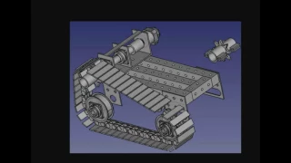
track.
Detail
subtract
detail,
so
the
track
consists
of
several
parts.
One
is
you
have
the
actual
track
pads
the
actual
tracks
tracks
proper
the
track
pads?
A
You
have
an
idler
which
is
those
wheels
that
the
tracks
are
just
right
on.
They
don't
drive,
but
there's
the
drive,
sprocket,
there's
a
tensioner
and
then,
of
course
you
would
have
mounting
two
wheels.
You
know
mounting
to
the
frame
but
track
detail.
Let's,
let's
go
through
some
of
this,
because
all
these
things
are
critical,
like
the
tensioner.
How
do
you
do
that?
The
drive
sprocket
is
obviously
the
most
important.
That's
how
you're
driving
you're
taking
the
power
from
the
motor
into
the
trucks
themselves.
The
idler
is
what
the
tracks
actually
roll.
A
Typically,
if
you
see
tracks
all
those
small
wheels
on
the
bottom,
they're
the
idlers,
meaning
where
the
tracks
just
smoothly
ride
on
them,
so
the
tracks
don't
fall
off
your
drive.
Assembly
and
trackpads
are
the
actual
actual.
You
know
two
inch
by
maybe
twelve
inch
pieces
or
like
an
slide
number
for
the
track
pads
or
just
to
label
that
explicitly.
A
Trackpads
are
the
multiple
units
of
which
we
need
many,
so
trackpads
and
then
actually
I'm
actually
going
to
bring
to
the
table
the
idea
of
rubber
printed
tracks.
So,
while
those
are
the
tracks
themselves,
they're
metal
right
there,
we
can
actually
talk
about
3d
printed
rubber
tracks.
So
so
those
are
the
track
pads.
A
A
A
A
Let's
first
first
item
just
covering
like
how
the
track
is
driven
is
sprocket
the
drive
sprocket
and
let's
go
to
a
working
document
here,
so
so
actually
that
sprocket
what
we
have
done
last
year.
Is
you
see
that
that
that
clamp
there,
the
sprocket,
was
actually
clamped
on
to
the
universal
rotor?
It
was
not
bolt
like
wasn't
keyed
in,
like
is
actually
a
bolt
on
connection,
so
it's
a
quick
disconnect
sprocket.
Now
that
worked.
So
let's
look
at
the
details
of
that.
A
So
basically,
what
we
did
is
is
bolt
clamp
it
with
this
large
clamp
here,
the
sprocket
to
the
shaft.
So
it's
a
very
easy
on
and
off
modular
mechanism.
You
can
think
of
it
as
you
take
that
off
and
you
can
put
instead
of
this
drive
sprocket
you
can
put
on
a
wheel.
So
you
have
quick,
disconnect
or
quick
interchangeability
of
what
of
how
you're
driving
this
this
tractor
thing
so
so
to
show
more
details
about
that.
A
A
A
A
A
What
I
was
talking
about
last
time?
You
can
stack
them
and
stack
them
various
ways.
You
can
stack
them
side
to
side.
You
can
train
them
with
a
train
of
them
together.
Things
like
that,
let's
see,
what's
what's
important
in
this
document,
what
I
wanted
to
get
to
was
the
actual
drive
sprocket,
so
the
only
information
we
have
about
that?
A
A
A
So
this
is
what
we
have.
This
is
what
we
did
before
and
the
idea
there
is.
We
got
to
cat
it
up,
so
this
is
basically
three-inch
yeah.
This
is
exactly
what
we
did.
This
is
three
inch
flat
tubing
like
half
inch
wall.
There's
your
shaft,
which
is
three
inch.
Shaft
get
your
sprocket
in
the
middle,
and
this
this
is
very
strong.
It's
got
4,000
pounds
of
torque
from
just
this.
A
This
thing
at
the
point
is
it
works
like
nobody
really
does
it
that
way,
but
it
works
for
us.
It's
the
modularity
idea.
You
can
take
this
on
on
and
off
quickly.
Okay,
so
I'm
going
to
go
back
to
this,
so
the
sprocket,
the
detail
is
already
in
last
years.
There
was
two
ago
document
we
need
to
cat
it
up.
So
that's
the
sprocket
that
driving.
A
You
can
talk
about
work
workflow
allocation
later,
but
let's
just
talk
about
explaining
this
to
everybody,
so
there's
the
sprocket
so
that
now,
let's
move
on
to
the
actual
track
pads,
that's
what
you're
driving
it
the
track
is
essentially
a
chain.
It's
a
chain
that
that
sprocket
drives
so
think
about
it
as
a
chain
like
a
bicycle
chain.
A
A
Rotation,
stuff,
I,
don't
have
much
more
work
on
the
track
in
this
document
so
but
this
document
does
link
to
the
actual
other
document,
which
I
believe
is
right
here.
The
bulldozer
design
link
on
page
number,
one
of
the
bulldozer
modules
working
document.
What
we're
concerned
about
and
I
can
start
drawing
this
up
right
now,
the
trackpads.
A
A
A
A
Okay,
so
here's
the
actual
drive.
Well,
that's
the
drug,
sprockets
3d
printed
them
to
test
amount,
how
they
work.
They
work.
Well,
it's
actually
an
open
scanned
file,
there's
a
sprocket
generator
on.
If
you
do
openscad,
which
is
the
open
source
parametric
software,
you
can
actually
generate
these
sprockets
and
we've
done
that.
So
that's
easy!
Here's
more
detail
detail!
So
let's
talk
about
the
industry
standards
of
tracks,
their
pad.
There
they've
got
there
like
a
chain.
A
You
can
see
the
diagram
of
sprockets
versus
idlers.
Well,
that's
how
they
look
so
the
tracks
are.
The
pads
are
driven
by
the
sprocket
through
a
hole
in
the
track
itself.
So
that's
what
actually
well
not
a
hole.
It's
no!
Let's
go
next!
Next
slide,
actually
next
slide
to
explain
how
they
work.
It's
not
that
the
hole
just
allows
the
sprocket
to
to
go
through
if
that
sprocket
is
too
too
tall
anyway,
that
what
drives
the
track
is
the
fact
that
the
sprocket
is
pushing
against
these
pins
here.
So
that's,
what's
actually
happening.
A
A
No,
that's
all
we've
got
for
the
tracks,
so
what
we
will
make
is
something
that,
as
far
as
the
actual
build
here,
what
we
do,
let's
copy
these
two
two
things
into
the
new
work
document
and
expand
on
that,
because
we
did
the
first
prototype
last
year
and
what
we
ended
up
with
is
is
with
a
design
that's
similar
to
to
this.
This
track
detail.
We
got
the
drive
cog,
an
actual
trackpad
and
so
forth.
This
is
this
is
how
it
ended
up
looking.
A
So
you
can
kind
of
try
to
picture
that
and
reconcile
that
against
this
document
here.
So
we've
got
the
pads.
You've
got
this
chain
like
element
and
so
forth.
So
but
that's
this
is
what
the
individual
piece
kind
of
looks
like
it's
similar.
That's
not
ours,
it's
similar,
but
each
of
these
pieces
want
fits
into
the
next
like
they
they
all
go
into
each
other
and
they
all
together
make
a
chain
with
a
pin
through
through
this,
and
what
we
want
to
do
this
time
around
is
improve
on
that
improve
on
what
we
have
done.
A
A
We
can
do
this
this,
and
this
is
what
we
want
to
cat
up
in
detail.
So
you've
got
these
two
pieces
like
those
pieces
of
metal
that
are
now
in
this
picture.
Standing
up
vertically
and
the
pin
the
actual
bolt
through,
we
can
use
a
simple,
regular
bolt.
So,
if
you
think
about
a
simple,
regular
bolt,
let
me
expand
that
view,
so
I
can
actually
draw
it.
A
A
A
A
So
think
about
it,
just
a
bunch
of
these
pads
together
so
they're
putting
put
right
next
to
each
other
and
that's
how
you
make
a
track.
It's
a
lot
of
work.
That's
where
you
need
CNC
cutting,
but
that's
what
you
do
and
then
to
get
more
traction
you
can
weld
like
here.
You
see
just
flat
track
pieces.
You
can
weld
a
bar
across
that
maybe
like
a
half
inch
or
one
if
we
actually
did
two
inch
vertical
pieces.
That
was
a
rough
ride.
A
Reinforcement
like
what
you
see
on
the
bulldozer
tracks,
they
have
this
vertical
part
coming
up,
so
you
get
better
traction,
but
that
thing
is
not
too
big.
It's
maybe
here
it's
like
one
inch
or
something
for
these
big
bulldozer
tracks.
Okay,
so
that's
the
tracks,
ideas.
This
needs
to
be
catted
up
and
then
we
move
on
to
there's
the
idlers.
The
idlers
we
have
once
again
the
design
is
pretty
complete
on
that.
If
we
go
to
the
let's
see
the
bulldozer
document,
the
sprockets,
the
idlers
they're
drawed
out
here
the
idler
wheels.
A
That's
all
we
did.
We
had
a
piece
of
8-inch
tube
and
we
put
the
bearings
on
them:
shaft,
collars
and
a
shaft.
Those
were
our
idlers
and
I
think
we
can
do
this
identically
as
we
see
here,
because
that
works
well
and
there
you
can
say
they're
the
idler
front
view
there.
That's
8-inch
diameter
for
the
inner
wheel
and
then
it
ends
up
being
like
the
effective
radius.
So
that
ends
up
being
twelve.
The
way
the
tracks
account
sit
on
it,
but
that's
the
either
just
freely
spinning
thing
that
rides
that
the
tracks
ride
upon.
A
So
that's
the
idler
next
part.
Is
it's
pretty
much
a
track?
What
else
are
we
missing
here?
We
have
more
pieces,
drive
sprocket
track,
pads,
idler
tensioner,
mounting
to
the
frame
3d
printed
track,
so
tensioner
and
mounting
to
the
frame
is
the
next
things.
If
we
talk
about
mounting
to
the
frame,
I
can
point
to
here.
A
Mounting
is
this
mounting
plate
right
there
that
basically
there's
two
of
those
plates
and
the
idler
goes
into
two
of
those
plates
like,
let's
see
if
we
can
see
it
in
this
picture
here
right
if
you
zoom
in
let's
zoom
in
on
this
detail
here,
because
that's
the
idler
right
there.
This
thing
right
here
is
the
idler.
A
So
what
you
see
for
the
idlers
there's
this
one
plate
here
and
actually
there
was
another
plate
here,
I,
don't
know
why
I'm
not
seeing
that,
but
it
sits
there,
because
this
idler
has
to
be
supported
when
you
have
a
shaft
get
to
support
it
on
two
points.
Otherwise
it
would
just
wobble.
So
you
got
two
of
these
vertical
plates
here,
supporting
the
idler
going
here
this
one
plate
here
and
then
the
second
plate
should
be
right
there
and
it
might
be
cut
off
there
for
some
reason.
A
A
When
you
mount
the
tracks,
they're
mounted
on
to
idler
sets
and
those
are
the
plates
to
the
frame
and
then
there's
the
the
rotor,
which
was
another
mounting
point,
so
that
track
is
supported
on
three
points.
It's
firmly
connected
to
the
frame.
So
that's
the
mounting
system,
but
you
got
to
remember
about
all
those
plates,
so
you
can
say
mounting
plates
to
for
the
two
sets
for
idlers
and
one
set,
and
then
the
drive
rotor
that's
already
connected.
A
Okay.
Now
the
critical
part
here
is
tensioning.
How
are
you
going
to
tension
that-
and
this
is
where
we're
going
to
do
an
improvement
and
and
the
way
we
do
tensioning
last
year,
was
you
see
these
plates
here?
They
actually
have
an
elongated
slitted
hole.
So
what
we
did
is
we
put
tensioners
and
you
can
see
the
tension
is
very
clearly
in
here
the
tensioner
and
let
me
zoom
into
that.
What
we
did
was
have
yeah.
This
is
much
clearer
how
this
works
here,
but
the
tensioner
was
basically
we
were.
A
A
So
sorry,
there's
this
one
plate
here,
the
other
plate
is
actually
on
the
far
side,
because
this
shaft
goes
all
the
way
through
you
can
do
it
all
so
that
yeah
yeah
I
take
back
what
I
said
before
about
the
two
plates
close
to
each
other,
that's
not
as
firm
as
two
plates
they're
very
far
from
each
other.
So
you
have
a
very
firm
connection.
So
this
one
shaft
carries
this
idler
here
and
I
learned
on
other
side.
Then,
when
you
pull
that
whole
shaft,
you
can
actually
tension
the
track.
That's
what
we
did.
A
So,
let's
discuss
the
tensioning,
so
what
we
want
to
do
this
time
around
instead
of
the
long
elongated
plates
where
the
the
shaft
actually
moves
in
there,
that's
a
little
harder
to
execute
that
actually
moving
the
idler.
Sorry
moving
the
actual
drive
sprocket
sliding
that
back
and
forth
on
the
on
the
platform
to
tension
the
track.
So
how
does
it
look
like?
Let's
discuss
the
tensioning,
so
let's
track
connection
to
do
another
slide
so
track
tensioning.
A
A
Okay,
so
if
you
take
a
look
at
that,
that
would
be
like
say
your
tracks,
you
put
on
the
tracks,
you
have
to
put
a
at
the
end.
You
connect
the
last
two
pins
and
you
bond
the
tracks
together.
You
can't
do
that
at
full
tension
of
the
track.
So
what
you
might
start
out
with
is
something
like
this,
where
the
tracks
here
are
relatively
loose,
they're
kind
of
dangling,
you
know,
so
you
can
put
them
on
their
loops,
but
you
got
tension
them
at
this
point.
A
A
They're
so
detention
the
track.
So
this
looks
like
it's
tensioned,
whereas
here
is
it's
floppy,
it's
like
that,
and
we
just
put
the
track
on
because
remember
this
is
human
scale.
This
is
design
that
said
everything
here,
the
rotors
every
part
weighs
no
more
than
200
pounds.
In
other
words,
one
strong
person
or
two
people
can
lift
that.
So
we're
not
designing
the
use
of
hoists
into
the
maintenance
aspect
of
the
of
the
track.
So
that's
what
it
happens
here.
The
tracks
get
tensioned
by
this,
so
move
the
actual
drive.
A
That's
the
idea:
now:
how
do
you
do
it
so
because
that
universal
rotor
up
there
sits
on
top
of
the
frame?
You
can
slide
that
across
the
frame,
so
the
universal
rotor
the
way
it's
attached.
It
looks
kind
of
like
that.
It
sits
like
your
universal
rotor
assembly,
which
you
can
represent
by
this
square.
A
So
you
essentially
slide
that,
on
top
of
the
slide
that
Square
assembly
on
top
of
the
frame,
you
still
need
some
tensioning,
bolts
and
so
forth,
but
that's
the
design
that
we
want
to
do
so,
that's
conceptually
what
we
have
for
the
track
tensioning
and
once
we
have
this
and
we
can
move
on
to
other
aspects
of
the
design.
So
so,
at
this
point,
going
back
to
slide
six
here.
A
You
want
to
use
just
the
motor
to
drive
things
so
then
we've
got
the
frame.
The
base
platform,
like
you
see
in
this
picture.
The
base
platform
here
was
very
simple:
that's
what
the
base
platform
looked
like
and
onto
that
was
where
everything
was
attached
from
the
wheels
to
the
power
cube
everything
else.
A
A
So
that's
the
idea
and
the
concept
here
is
once
we've
got
something
I
mean:
let's
talk
about
role
allocation
here,
but
for
now
we
don't
have
to
do
that.
Let's
go
to
the
meeting
proper.
Now
Ahmed
is
working
on
this,
so
Achmed.
If
you
see
this,
we
can
start
drawing
up
with
individual
parts,
but
this
would
of
course,
lends
itself
to
a
design,
sprint
or
other
thing.
Now.
The
priority
for
for
this
weekend
is
so
now
yeah
and
let's
actually
roll
into
the
next
meeting.