►
From YouTube: AWG Meeting 040423
Description
Presentation by Tim Edwards on updates to Magic extractor, as well as presentation by Stanley Lin on Comparison of Opamp Pre & Post-layout Performance Between Closed and Open tools
A
B
You
can
all
see
my
screen,
yep,
okay,
yeah,
so
I
last
talked
to
this
group.
Well,
a
couple
times
ago,
I
talked
to
this
group
about
extraction
and
magic,
and
some
of
the
research
I
was
doing
and
to
trying
to
figure
out
how
to
improve
Magics
extraction
that
was
back
in
August
30..
It's
been
a
little
over
seven
months
since
then,
and
I've
done
a
lot
of
work
on
that.
So
it's
worth
giving
an
update
to
that
and
having
a
few
more
details
about
full
RC
extraction
and
Magic.
B
So
as
so,
a
little
recap
on
what
I
talked
about
back
in
August.
The
problem
that
I
had
with
magic
at
that
time
is
that
it
had
a
simplified
model
of
French
capacitance,
in
which
it
was
assuming
that
all
Fringe
capacitances,
essentially
in
in
infinitesimal
area
along
the
line
on
the
border
of
a
metal
and
that
worked
way
back
in
the
day
when
magic
was
written
back
in
the
mid
80s
for
a
you
know,
one
or
two
Micron
process.
B
You
can
separate
out
your
plate,
capacitance,
which
is
an
easy
analytic
expression
and
then
add
that
to
your
branch
capacitance
and
assume
that
if
there
is,
for
instance,
here
you've
got
metal
two
on
top
metal,
one
on
the
bottom
and
the
metal.
One
is
shielding
your
capacitance
from
the
substrate
and
you
could
divide
the
shielded
part
again
between
the
part
of
the
area.
B
The
capacitance
I
was
trying
to
work
from
capacitance
tables
that
were
being
provided
by
the
foundries,
namely
Sky
water
and
figure
out
exactly
what
is
a
good
expression
to
use.
So
I
started
out
with
just
a
sort
of
hand,
waving
argument,
analytics
expression,
which
I
said:
okay,
the
it's
going
to
increase
the
French
pastants
incident
on,
say
here
from
the
edge
of
metal
two
down
to
metal
one
as
metal.
One
extends
out
from
underneath
metal.
B
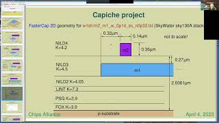
So
I
started
looking
at
this
modeling
tool
called
faster
cap,
which
is
a
3D
solver
and
I
could
use
that
to
set
up
the
whole
boundary
stack
up
for
the
in
this
case,
the
sky
130
process,
but
I
came
up
with
an
input
file
format
based
on
python,
which
I
could
describe
any
metal
stack
up
with
the
dielectric
layers
and
the
dielectric
thicknesses,
the
metal
thickness
and
height
sidewall
dielectrics.
All
of
that
could
be
described
in
the
input
structure
and
then
I
had
some
other
Python
scripts.
B
That
would
go
build
out
the
input
files
to
faster
cap
from
those
structures.
So
I
had
a
file,
and
all
this
is
in
the
the
I
call
this
a
capiche
project
and
you
can
find
it
on
GitHub
under
this
URL
under
my
name
and
the
Project's
name
is
capiche
and
it
has,
for
instance,
a
script
that
will
describe
a
metal
layer
on
top
of
another
layer
that
is
shielding
that
from
substrate,
and
then
you
can
Define
the
width
of
the
metal.
B
The
position
of
the
shielding
metal
underneath
so
I
could
use
that
to
have,
for
instance,
in
this
case,
where
I
have
Metal
2
over
metal,
one
have
metal
one
extending
out
to
something
like
40
or
50
microns
out
to
one
side,
which
is
effectively
infinite,
that
captures
99.9
something
percent
of
The
Fringe
capacitance.
On
that
side,
I'll
do
one
test
where
I
have
the
metal
extending
out
that
far
on
both
sides
and
I
get
the
total
fringed
capacitance
or
the
total
capacitance
metal.
B
One
metal
two
I
can
subtract
out
the
area
capacitance
assuming
they're
all
additive
and
then
divide
the
remainder
by
two.
So
I
know
what
the
Fringe
resonance
is
the
total
Fringe
on
one
side
and
then
from
the
remainder
I.
Can
go
figure
out
exactly
how
much
of
the
French
capacitance
is
incident
on
the
shielding
layer
underneath
according
to
faster
cap?
B
So
this
is
what
the
input
file
to
faster
cap
looks
like
graphically.
I've
got
one
metal
layer
described
here.
I've
got
all
my
dielectrics
described
all
the
values
for
the
dielectrics
put
in
the
substrate,
underneath
that's
what
goes
into
faster
cap.
This
is
the
visualization
of
it.
I
keep
track
of
all
these
files
in
the
capiche
project.
B
So
I
looked
at
this
graph
for
a
while
and
played
around
with
it
and
with
some
curve
fitting
and
decided
this
is
an
arc
tangent
and
that
for
every
set
of
wire
coupling
I
could
come
up
with
a
wire
over
a
shield
wire.
It
always
came
out
to
be
an
arc.
Tangent
and
I
could
model
that
accordingly,
so
I've
got
four
wires.
Four
curves
here,
one
of
them
is
faster
cap.
That's
the
blue
wire!
There
are
some.
B
There
are
a
few
issues
with
faster
cap
where
it
likes
to
switch
from
like
one
solution
to
another
solution
and
I've
talked
to
the
developer
of
faster
cap.
I
think
I
need
to
do
some
things
where
I
record
the
the
first
solution
to
faster
Capital
use
that
is
input
to
other
Solutions.
So
there
are
various
ways
that
I
could
probably
speed
up
and
make
it
more.
C
Yeah
sure
go
ahead,
Tim
when
device
people
find
a
curve
like
this.
They
prefer.
You
know
what
I've
learned.
They
prefer
to
model
it
as
one
over
one
plus
x
to
the
power
of
n
and
then
in
truth
of
that,
because
floating
Point
processors
tend
to
deal
with
it
faster
than
with
our
tangents
and
other
trig
functions.
B
B
B
B
B
So
anyway,
thanks
I'll
for
the
purposes
of
this
presentation,
I
will
continue
talking
about
the
Archangel,
though
yeah.
So
this
is
my
replacement
function
for
the
partial
Fringe
capacitance
I've
got
a
using
the
arc.
Tangent
I'm
scaling
it
to
one
over
to
zero
to
one.
So
the
tangent
at
Infinity
is
pi
over
two.
B
B
So
it
is
probably
therefore
related
to
the
area
capacitance.
Now,
since
I'm
doing
the
fraction
I'm
getting
a
result
which
has
no
Dimension
dimensionless
argument.
So
if
I'm
going
to
relate
it
to
a
area
capacitance,
then
it's
going
to
have
to
be
area
capacitance
for
a
fixed
value
of
error
area
like
one
micron
squared
and
so
I
plotted
that,
and
indeed
it's
it's
exact,
so
I
don't
need
to
actually
preserve
a
coefficient
for
every
metal
layer.
B
B
So
how
much
of
the
capacitance
to
substrate
get
shielded
by
in
this
case,
I've
got
a
metal
layer
here
and
another
metal
layer
there,
and
so
there
is
some
amount
of
that
French
capacitance,
that's
being
shielded
for
the
purpose
of
doing
the
sidewalk
past
and
so
I
had
implemented
a
routine
in
Magic.
That
would
go,
find
the
edge
the
nearest
Edge
outward
from
any
edge
of
metal
and
then
use
that
those
divided
down
areas
to
compute
what
the
sidewall
capacitance
is.
B
One
is
the
same
here
as
it
is
here
when
you
extend
metal
one
and
no
matter
how
far
off
you
extend
the
metal
so
using
that
same
expression
for
dividing
up
or
the
same
routine
for
dividing
up
the
areas
for
the
sidewall
capacitance
I
could
use
that
same
routine.
To
say
all
right.
This
is
the
area
that
is
essentially
a
partial
capacitance
for
The
Fringe
from
metal
down
to
substrate
and
everything
behind.
B
So
that's
the
state
of
the
Magic's
routines
for
calculating
Fringe
and
all
types
of
parasitic
capacitance.
The
my
issues
right
now
is
whether
I
have
all
the
information
I
need
to
plug
into
capiche.
To
give
me
all
of
the
coefficients,
I
need
out
of
it.
Gf
is
is
very
good.
It
has
given
me
not
only
a
stack
up
in
the
open
source
documentation,
but
stack
up
plus
the
Deltas
for
the
high
and
low
Corners
Sky
130
doesn't
have
the
Deltas
for
the
high
and
low
Corners.
B
B
But
once
you
have
those
values,
all
the
just
running
capricias
pretty
much
automated
process
and
I
can
just
crank
out
the
coefficients
that
I
need
for
Magic
and
I.
Think
Stanley
will
give
some
results.
That
appears
that
it's
getting
reasonably
good
results,
so
I
think
it's
supposed
to
be
within
a
few
percent
of
what
you
could
get
out
of
commercial
tools,
and
that
seems
to
be
the
case
so
onward
to
the
full
RC
parasitic
extraction.
This
is
the
Fairly
lengthy
set
of
commands
and
Magic
that
you
need
to
do
a
full
rcx
extraction.
B
I've
been
able
to
do
full
RC
extraction
on
some
fairly
large
circuits,
so
I
did
one
on
a
one
caliber.
No
one!
Kilobyte
SRAM
from
the
open
Ram
project
and
was
actually
able
to
get
a
a
meaningful
result
out
of
that,
although
the
thing
was
at
least
100
megabytes
spice
and
I
tried,
simulating
it
in
NG
spies
for
several
days
and
it
never
really
started
up
the
transient.
B
So
I
have
some
work
to
do
to
figure
out
how
to
get
something
like
that
to
simulate
magix
algorithm
for
the
resistance
extraction
has
been
in
there
for
quite
some
time.
I
think
it
dates
back
to
around
1990,
maybe
if
not
before,
but
it's
fairly
straightforward.
What
it's
doing
is
it's
going
through
all
of
the
geometry
sort
of
a
three-step
process.
The
first
step
is
to
figure
out.
Where
are
your
grains
of
sources,
all
the
terminals
of
any
device
so
find
your
drains?
B
Your
Gates,
your
sources,
your
substrates
and
then
and
your
drive
points
which
would
be
like
a
pin
and
then
from
that
determine
which
way
the
current
is
flowing,
and
once
you've
got
the
all
that
information.
You
can
overlay
your
geometry
with
some
directed
graph
that
says:
okay.
This
is
the
way
the
current
is
flowing
through
each
of
these
wires
and
then
from
that
figure
out.
B
B
This
is
the
one
ksram,
but
Matt
good
house
sent
me
this
little
tiny
SRAM,
which
has
just
like
I,
don't
know
like
a
eight
by
eight
or
something
set
of
cells,
and
it's
small
enough
that
I
can
extract
the
thing
in
a
few
seconds.
So
it's
fairly
easy
to
work
with,
and
does
it
take
all
day
to
do
extractions,
so
I
I've
been
spot
checking
by
saying.
Okay,
look!
Here's
some
kind
of
long
line
in
here
now.
What
is
what
is
Magic's
RC
extraction
producing
for
that?
B
B
So
it
you
know
just
doing
basic
spot
checks
of
of
wires.
It
looks
like
the
answer
is
valid.
I
have
not
yet
seen
anything
that
would
suggest
that
it's
producing
invalid
results
now
Stanley
is
going
to
give
a
Counterpoint
to
that.
So
there
is
probably
plenty
of
Investigation
to
do.
There
are
many
ways
that
this
could
be
going
wrong.
The
main
way
it
would
be
going
wrong
is,
if
it
fails
to
determine
which
direction
the
current
is
Flowing.
B
You
could
get
a
wildly
incorrect
answer
for
any
segment
of
your
graph
as
I
said
I.
In
my
spot,
checks,
I
haven't
found
that
out
yet,
but
if
I
have
some
counter
examples
to
work
with
I'll,
definitely
investigate
if
magic
is
not
producing
the
right
answer.
It's
my
goal
to
make
sure
it
does
so
anyway.
That
is
my
presentation
for
where
the
state
of
things
are
right
now
and
thanks
for
listening,
we
can
either
go
on
to
Stanley's
presentation
right
now
or
I
can
take
questions
and
answers
now.
A
C
C
C
A
So
it's
a
you're
saying
this
is
a
compiler
right.
I
I
would
call
it
a
generator,
a
generator
good,
okay.
Well,
thanks
for
sharing
so
yeah,
so
there's
a
bunch
of
things.
I
wanted
to
mention
here
which
are
basically
having
some
test
structures
to
help
the
work
done
by
a
team
team
here,
but
also
there's
Matthias
from
K
layout
I.
Don't
think
his
mic
is
working
for
some
reason,
but
basically
developing
tiles.
A
So
people
can
have
silicon
data
like
on
simple
structures
and
then
correlate
with
whatever
models
Tim
is
using
could
be
very
beneficial
and
to
help
us
it
will
help
us
close.
The
loop
between
you
know,
design
and
technology
and
models
and
basically
decouple
all
the
issues
we've
been
seeing
with
these
open
source
tools.
A
D
Okay,
thank
you.
So
thank
you
for
having
me
to
give
this
short
presentation.
So
what
I've
done
is
based
on
our
op-amp
in
GF
180.
In
order
to
see
the
actual
simulation
result,
we
ran
the
signal.
We
again
ran
the
simulation
on
the
close
tool,
so
in
my
presentation,
I
will
first
introduce
our
circuits
and
show
you
the
comparison
results
and
then
I
will
and
then
I
try
to
do
some
preliminary
checking
in
for
some
simple
circuits
and
I
will
show
you
in
the
end
of
the
presentation.
D
So
I
will
so
I
extract
the
parasitic
from
both
tools,
close
tool
and
open
source
tool
to
see
if
there
is
any
discrepancies.
So
this
is
the
parasitic
extraction
command,
I
use
in
Magic,
I.
Think
Team
just
mentioned
this,
so
I'll
skip
this
part,
and
this
is
the
capacitance
comparison
between
these
two
tools
and
you
can
see
the
value
the
value
of
capacitance
on
at
least
some
nodes,
coupling
capacitors
here
and
you
can
see
at
some
nodes.
There
might
be
a
large
discrepancy,
and
this
is
the
total
resistance.
D
So
the
problem
is
that
when
I
use
the
python
script
to
sum
up
the
resistance
in
the
same
node,
so,
for
example,
the
this
circuit
showing
below
the
ideal
value
should
be
are
in
parallel
with
3r,
but
in
my
script,
I
I
just
sum
up
these
resistance
resistance,
so
the
total
resistance
showing
in
my
Python's
grid
would
be
4r
so
so
for
now,
I
think
for
me,
it's
hard
to
analyze
the
total
resistance
on
the
complicated
layout,
because
you
don't
know
the
parasitic
resistance
would
be.
You
know.
D
Some
resistance
is
in
parallel
with
some
other
resistance.
In
series
so
yeah
for
now
I'm
hard
to
analyze
the
real
total
resistance
for
a
complicated
layout.
Okay.
So
let's
go
to
the
simulation
results,
and
this
is
the
test
bench
I
use
for
our
op-amp.
So
it's
basically
with
a
DC
feedback
to
set
up
the
outputs
voltage
comma
mode-
and
this
is
the
pre-layout
simulation
result
you
can
see.
D
Almost
all
the
performance
are
the
same
between
the
close
tool
and
the
open
source
tool,
and
this
is
a
post
layout
simulation
table
you
can
see
there
is
some
discrepancy
shows
up
and
this
so
there
are
like
a
few
percent
of
the
difference
and
which
is
due
to
the
different
parasitic
extracted
from
from
both
tools:
okay,
so
I
list
the
The,
increased
percent
of
difference
between
the
pre-layout
simulation
and
post
layout
simulation
and
so
yeah.
So
it's
a
it's
a
summary
for
the
simulation
I
just
mentioned.
D
So
in
pre-layout,
almost
there
are
almost
no
no
difference,
but
in
post
layout
this
different
shows
up,
because
the
discrepancy
in
from
of
the
extracted
is
from
both
tools
and
so
yeah.
That's
basically,
the
result
for
our
op-amp
and
I
actually
run
a
different
test
bench
on
the
op
amp,
which
is
the
unit
again
feedback
and
I.
Think
I
will
just
quickly
run
through
these
slides,
because
the
this
is
similar
with
the
with
the
simulation
I
just
presented
yeah.
D
So
this
is
pretty
little
simulation
and
you
can
see
just
like
the
previous
one.
The
almost
all
the
performance
are
similar,
and
this
is
the
policy
layout
simulation.
So
you
can
still
see
some
difference
caused
by
the
discrepancy,
and
so
I
want
to
mention
the
gain
error
here.
So
the
again
error
means
that
so,
for
example,
in
this
test
bench
that
ideal
gain
should
be
one
because
this
is
a
unit
to
gain
bandwidth.
D
So
the
gain
error
is
basically
means
that
how
much
gain
is
shipped
from
the
ideal
gain,
which
is
one
so
you
can
see.
The
gain
error
is
very
small
for
this
op-amp,
because
this
scan
error
comes
from
the
open
loop,
the
finite
gain
of
the
op
amp.
So
if
the
ideal
oil
pump
with
the
infinite
gain,
the
gain
error
should
be
zero
percent,
but
because
our
op-amp
is
fight.
D
Has
finite
gain
so
we
have
some
small
gain
error,
and
why
is
the
gain
error
is
so
small
is
because
that
our
looking
is
a
very
large,
even
Beyond,
100,
DB
and
100
DB
open
loop
game
can
actually
give
you
this
less
than
one
micro
percent
gain
error,
but
you
can
see
the
game
error
between
close
tool
and
open
source
tool
is
kind
of
large,
like
30.
That
is
because
how
we
calculate
it
like
if,
if
the
gain
has
a
little
bit
open
loop
gain,
has
a
little
bit
change.
D
That
will
give
you
a
large.
You
can
error
this
difference
yeah,
and
these
are
the
figures
for
the
op-amp
and
so
the
ball
at
least
I
put
the
poly
plug
and
noise
plot
here
versus
frequency,
and
this
is
the
gain
vs
Power
and
bandwidth.
Vs
Power,
just
like
I
said
our
functionality
of
the
op
amp
is
basically
on
the
game.
Bandwidth,
noise
and
power
trade-off
opanks,
which
is
which
means
that
you
can
operate
the
op-amp
under
different
power
and
you
can
get
different
gain.
D
So
this
is
the
pre-layout
figures
you
can
gain
you.
Can
you
can
see
that
the
gain
and
bandwidth
actually
increases
when
the
power
increases,
and
this
is
the
face,
margin
and
noise?
You
can
see
the
noise,
especially
through
the
noise.
When
you
increase
the
power,
you
can
get
lower
noise,
so
that
is
basically
the
function
function
of
this
old
pack,
and
so
this
is
the
layout
okay.
So
this
is
the
step
response
for
this
unit,
again
feedback
bandwidth.
So
you
can
see
the
the
op-amp
is
stable.
D
Okay,
so
I
just
quickly
run
through
all
the
figures,
and
this
is
a
post
layout,
step
response
and
post
layout
can
error,
BS
power
and
bandwidth.
Vs,
Power,
noise,
vs,
Power,
okay,
so
and
in
this
appendix
too
I
will
show
you
a
partial
screenshot
of
the
circuit
analyst.
So
this
is
the
pre-layout
circuit
netlist.
So
so,
in
this
slide,
I
want
to
show
you
that
there
is
some
something
in
NG
spice,
which
is
the
maximum
of
the
total
width,
is
100
micrometer
in
NG
spice.
D
So
if
you
have
a
large
device,
we
use
a
large
device
in
op-amp.
So
if
you
have
a
large
device,
Beyond
100
micro,
you
have
to
put
that
put
those
devices
in
parallel,
so
so
in
NG
spice
the
from
micrometer.
If
you
write,
if
you
have
a
line
with
Pro
micrometer
and
with
finger
equals
to
four
that
will
give
you
some
error,
messages
to
edgespace
will
show
you.
There
is
something
happens
in
your
English
slide,
and
this
is
an
extracted
analyst
from
the
close
tour
and
open
source
tool.
D
So
you
can
see
just
like
the
general
netlist
there's
a
bunch
of
RNC
there
and
and
and
then
I
so
I
run.
The
extraction
here
is
some
extraction
examples.
So
first
example
is
a
simple
common
source
amplifier,
which
is
showing
here.
So
this
is
a
nmos
fet
with
a
passive
load
and
on
the
right
side,
is
its
layout,
so
I
first
extracted
the
Nellis
from
Magic.
So
in
the
middle,
is
the
exact
in
the
list
extracted
from
Magic
and
I
manually.
Convert
this
netlist
to
the
schematic
on
the
right.
D
So
you
can
see
here
is
some
parasitic
resistance
in
series
and
the
capacitance
on
each
node.
Okay,
so
then
I
try
to
extract
the
Nellis
in
close
tool
and
I.
Show
you,
the
partial
netlist,
because
the
nail
is
generated
from
the
close
tool
is
way
more
complicated,
comparing
to
the
nearest
generated
from
from
Magic
and
so
for
this
close
to.
Fortunately,
it's
not
much
more
complex.
D
So
let's
compare
the
schematic
from
the
magic
and
from
the
closed
tool,
so
at
least
I.
So
these
two
schematics
is
showing
here
so
actually
I
simplified
the
previous
schematic,
so
yeah
I
try
to
like
combine
again
the
resistance
in
series
in
parallel
and
calculate
value
and
combine
the
capacitance
in
parallel.
So
here
is
the
result
of
these
parasitic
value.
So
you
can
see
the
close
tool
actually
has
a
larger
parasitic
and
it's
basically
so
for
the
both
RNC.
D
D
This
some
difference
shows
up
and
you
can
see
that
the
result
from
anti-spice
is
actually
the
bandwidth
from
the
NG
spice
is
actually
larger
than
close
tool
and
which
is
which
meets
our
observation
here,
because
the
close
tool
has
a
larger
parasitic
so
might
have
a
lower
bandwidth
and
it
will-
and
this
discrepancies
will
give
you
3.9
percent
of
difference
on
the
bandwidth
between
both
tools
Okay.
So
next
I
will
show
you
the
next.
D
The
second
example
switching
is
an
inverter,
so
this
is
a
schematic
inverter
and
on
the
right
side,
is
the
layout
of
this
inverter,
so
yeah
I
use
the
same
steps
to
to
analyze
the
parasitic
resistance
and
capacitance
and
just
like
the
common
source
amplifier.
This
inverter
has
its
not
much
complicated
nail
list,
so
I'm
able
to
calculate
all
the
resistance
and
capacitance
here.
So
compare
with
the
schematic
from
Magic
the
schematic
from
the
closed
tool
actually
has
a
larger
piracy
Scenic,
just
like
the
common
source.
D
And
it
will
give
us
around
4.6
percent
difference
so
and
and
in
order
to
so
I
simulate
again
with
a
different
loading.
So
in
this
slide,
I
replace
the
20
femto
to
to
femtole
to
see
how
does
the
circuit
change?
How
does
the
simulation
result
change
due
to
the
loading
the
value
of
loading
change?
So
actually,
so
you
can
see
a
larger
diff
difference
when
I
replace
the
loading
with
a
smaller
one,
so
it
will
give
us
like
8.8
percent
of
difference
between
open
source
to
Tool
and
close
tool.
E
A
E
Work
the
I
mean
it
does
point
that
this
is
going
to
be
an
uphill
battle
to
build
trust
in
any
of
these
tools
right.
They
have
certainly
as
compared
to
the
ones
where
The
Foundry
is
responsible
for
the
rule,
deck
that
goes
into
them
and
you
know
commits
to
supporting
an
extraction
deck
in
a
particular
tool
and
I.
Think
you
guys
have
the
right
and
generally
requires
a
lot
of
silicon
and
a
lot
of
kind
of
calibration
and
testing
to
sort
of
get
it
right
and
I.
E
E
E
So
this
is
a
thought
more
than
a
question,
but
it
would
be
great
if
we
could
compile
some
of
those
and
find
some
great,
some
more
means
of
sharing
them
right.
Some
means
of
saying
these
are
kind
of
the
important
test
circuits.
Some
of
them
will
be
just
kind
of
geometry.
Some
of
them
will
have
devices
and
yeah.
A
I
agree
with
that
then
I
think
Michael
earlier
was
basically
to
see.
If
there's
anyone
in
the
group
who
wants
to
help
us
Define
these
test
structures,
I
mean.
Obviously
some
of
them
are
very
obvious,
but
getting
some
expertise
there,
especially
from
the
model.
Folks
or
you
know,
any
other
members
who
wants
to
contribute,
please
reach
out
and
we'll
definitely
make
the
structures
we
made,
some
of
them
in
mpw5
in
skywater
and
hopefully
we'll
make
someone
GF.
But
if.
F
F
A
G
I'm
just
curious,
I
think
I
think
dance
comments
were
spot
on,
I
mean
I,
know
in
general,
you
know
when
in
spark
engineering
and
also
back
in
IBM
right,
we
would
do
test
circuits.
That
would
then
go
into
test
Wafers
that
we
would
then
get
measurements
on
and
then
use
that
to
help
calibrate
the
tools
or
upgrade
the
algorithms
as
needed.
A
G
C
Dan
had
it
spot
on
and
just
to
add
to
that
anecdotally.
If
we
were
looking
at
this
at
some
point,
you
know
we
did
some
variability
studies
and
in
in
other
processes,
I'm
15
years
ago
or
so,
and
and
you
know,
then
we
were
made
aware
of
the
structures
that
commercial
industry
uses
to
to
you
know
calibrate,
caliber
and
and
other
tools
they're
fairly
elaborate.
C
C
What
I
was
told
after
that
is
that,
in
order
to
validate
that,
you
need
about
20
Lots
to
you
know
to
to
actually
populate
the
caliber
model,
and
that
costs
quite
a
bit
of
money,
and
then
you
know
quite
a
bit
of
over
processing
time
after
that,
the
so
the
question
here
is
you
know
what
would
be
the
minimum?
You
know
I'm,
assuming
that
we
don't
have
funding
to
develop
that
kind
of
a
test
structure
that
would
compete
with
with
the
caliber
and
by
the
way
either.
C
C
The
question
here
is,
and-
and
that's
also,
these
20
locks
Lots
were
cited
with
respect
to
qualifying
yes,
Ram,
a
different
type
of
an
SRAM.
You
know
extraction
associated
with
with
the
master
and
parasitics.
The
question
here
is:
what
is
the
minimum
set
that
we
need,
and
how
do
we
get
to
that
minimum
set?
B
A
A
B
Anything
that
shows
a
discrepancy
of
around
10
or
so
or
more
is
going
to
be
helpful,
because
it's
something
I
can
look
in
and
immediately
see
what
the
problem
is.
I
would
like
to
knock
down
the
discrepancies
to
under
five
percent
in
all
cases,
if
I
can
sure
so
something
like
this,
and
in
fact
this
is
sort
of
expected.
I
do
know
that
there
are
the
one
issue
that
I've
seen
and
the
resistance
extraction
is
that
sometimes
magic
is
ignoring
things.
B
C
It
is
worth
looking
at
that
I
can
try
I,
think
I,
believe
it's
Keith
Jenkins,
who
retired
soon
afterwards,
you
know,
went
on
you
know,
publishing
and
basically
IBM
did
not
open
source
them,
because
there
was
no
way
of
open
sourcing
them,
but
they
went
out
and
published
met
several
venues,
structures
that
were
they
were
using
for
extraction,
that's
something
that
is
worth
looking
at
again.
I
repeat,
those
are
uncommon
ways,
some
of
less
common
structures.
You
know
more
of
IBM
Style.
A
G
B
A
A
Right
so,
in
any
case,
in
the
background
we
are
trying
to
put
together
proposals
and
the
work
to
be
done
here.
So
please
remember
to
reach
out.
If
you
have
some
ideas
or-
or
you
know,
resources
we
can
use
for
this.
This
work
here
and
I
think
in
the
future.
This
is
going
to
be
an
automated
process
where
we
can
reproduce
it
in
different
Technologies
that
are
going
to
be
open
source.
Hopefully,
so,
let's
see
all
right
thanks.