►
From YouTube: N8UR PSWS CKM Status Feb2021
Description
John Ackermann N8UR updates the status of the clock module that can be used for Tangerine SDR and stand-alone.
Find out more at https://tangerinesdr.org
A
Hi,
this
is
an
update
on
the
status
of
the
tangerine
sdr
gps,
disciplined
oscillator
clock
module
the
clock
module
for
the
tangerine
sdr
has
to
provide
accurate
and
stable
sources
of
several
signals,
as
shown
here.
A
gps,
disabled
oscillator
is
the
best
way
to
accomplish
both
the
accuracy
and
the
stability
that
we
need.
A
So
just
as
a
quick
refresher,
a
gps
disciplined
oscillator
takes
advantage
of
the
fact
that
the
gps
pulse
per
second
signal
you
can
get
from
many
receivers
is
noisy.
It
has
a
lot
of
jitter
in
the
short
term,
but
in
the
long
run,
attracts
the
atomic
clocks
at
the
u.s
naval
observatory
in
the
national
institute
of
standards
and
technology.
A
A
This
chart
on
the
right
shows
how
this
works.
This
is
an
deviation
plot.
You
can
think
of
length
deviation
as
sort
of
like
standard
deviation,
although
technically
it's
not.
The
x-axis
is
time
logarithmically
from
one
second
to
a
hundred
thousand
seconds.
The
y-axis
is
free
as
fractional
frequency
difference.
It's
a
a
version
of
parts
per
million
or
percentage
the
lower
on
the
y-axis.
You
are
the
better
for
performance
for
it's
higher
stability
low
on
the
chart.
A
As
we
look
at
this,
the
blue
line
is
the
pulse
per
second
output
from
a
traditional
good
quality
gps.
The
violent
line
is
a
temperature
compensated
crystal
oscillator,
and
the
green
line
is
an
inexpensive
ebay
of
an
oscillator.
You
can
see
that
the
gps
signal
just
keeps
getting
better
over
time.
That's
because
the
noise
is
averaged
out
and
we
get
closer
to
the
atomic
clock
performance,
whereas
beyond
the
crystal
oscillators,
both
are
sort
of
flat
at
short
term,
but
then
they
start
to
trend
upwards
as
drift
and
other
factors
enter
in.
A
A
A
After
working
on
that,
I
was
working
on
some
tests
on
some
modern
u-blox
gps
receivers,
and
we
learned
about
maybe
a
simpler
way
to
do
things.
The
u-blox
receivers
have
a
time
pulse.
Output,
that's
normally
set
to
pps
one
pulse
per
second,
but
it
can
actually
be
programmed
to
more
than
10
megahertz
on
these
modules.
The
output
of
the
time
pulse
at
rf
frequencies,
like
10
megahertz,
is
remarkably
good.
It's
actually
much
better
than
the
pulse
per
second
output,
but
there's
a
lot
of
jitter
on
the
10
megahertz
signal.
It's
phase.
A
Noise,
sucks
and
you'd
never
be
able
to
put
that
signal
on
the
air
because
it
would
just
be
too
too
ugly
but
separately.
I
learned
that
there
is
a
series
of
chips
manufactured,
I
think
mainly
for
the
telecom
industry
that
are
called
jitter,
attenuators
and
they're,
designed
to
be
used
as
part
of
the
clock
distribution
system
in
large
digital
systems.
Basically,
you
have
one
master
clock,
that's
driving
a
whole
bunch
of
boards
and
each
board
needs
to
generate
its
own
clock
frequencies
and
needs
to
clean
up
all
the
noise.
A
That's
on
the
master
clock
signal
after
it's
bouncing
around
the
room
and
these
jitter
attenuator
chips
do
that
they
have
an
external
oscillator
of
their
own.
That's
used
to
provide
the
short-term
stability
and
the
phase
noise
of
the
output,
while
being
locked
to
the
reference
signal.
That's
coming
in
from
the
external
clock,
so
you
actually
have
a
phase
lock
loop
and
it
works
a
little
bit
like
a
gps,
dl
mic.
A
The
chips
provide
multiple
outputs
at
anything
from
100
kilohertz
to
over
a
gigahertz,
and
there
are
several
outputs
available,
depending
on
which
chip
you're
using
so
based
on
those
ideas.
We
started
from
scratch.
With
the
mark
ii,
clock
module
we're
going
to
use
a
u-blox
gps
time
pulse
at
10
megahertz,
that's
fed
as
the
input
signal
to
a
silicon
labs,
5345,
jitter,
attenuator
chip,
the
pll
on
that
chip
is
actually
acting
like
a
gps.
A
Do
the
output
of
the
chip
is
synthesizes,
the
frequency
we
want
and
that's
locked
to
the
10
megahertz
input,
but
its
phase
noise
is
significantly
cleaned
up
and
the
5345
chip
is
great.
It's
got
10
independent
outputs
and
it
can
directly
provide
all
the
tangerine
sdr
clocks
plus
a
whole
bunch
left
over
to
use
for
other
things.
If
we
want.
A
This
is
a
block
diagram
of
the
mark
ii
system
and
you
can
see
it's
way
simpler.
Just
a
gps,
feeding
the
5345
chip,
the
output
to
the
5345,
going
to
an
interface
connector,
along
with
a
pulse
per
second
for
the
gps,
and
also
the
serial
data
screen
for
the
gps,
so
that
are
all
made
available
to
the
other
side
of
the
bus.
A
A
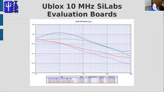
The
violet
is
the
last
generation
timing-
receiver,
that's
probably
60
to
70
today
and
the
green
is
the
current
generation
receiver,
which
has
a
lot
of
new
features,
and
it's
about
150.
You
can
see
that
the
more
you
pay,
the
better
performance
you
get.
So
things
are
working
as
we
might
expect
we're
going
to
make
the
clock
module
available
with
any
of
these
three
options
installed,
so
it'll
sort
of
be
a
bronze
silver
and
gold.
A
Depending
on
how
much
you
want
to
spend
for
the
module,
we
fed
the
10
megahertz
output
from
the
best
quality
of
those
receivers,
the
the
current
generation,
a
timing
receiver
into
the
silicon
labs
chip
evaluation
boards-
and
actually
I
have
two
two
of
those
boards.
One
is
for
the
53
35
series
chips.
The
other
is
for
the
last
generation
5328.
A
Now.
The
trade-offs
of
this
designer
are
these.
On
the
pro
side,
it's
much
simpler.
There's
no
fpga
programming
required
and
the
cost
of
the
non-gps
components
is
much
less,
so
that
makes
it
less
painful
to
use
a
better
quality
gps
module
and
it
gives
us
huge
frequency
agility
with
10
outputs
and
any
kind
of
frequency.
We
want
basically
from
100
kilohertz
to
a
gigahertz.
A
The
con
side
is
that
the
crystal
oscillator,
that's
used
by
the
chip
is
in
the
40
to
50
megahertz
range
and
it's
quite
difficult
to
find
a
wide
range
of
choices
of
tcxos
or
oven,
controlled
oscillators
at
that
frequency
and
there
they're
significantly
more
expensive.
So
we
don't
have
a
lot
of
choice
in
the
oscillators
we
can
use
to
improve
performance
and
also
the
jitter
attenuator
chip.
Pll
has
a
loop
bandwidth
that
goes
out
to
about
a
tenth
of
a
hertz
or
somewhat
less
than
that,
and
that's
fine
for
moderate
performance.
A
So
this
design
is
not
really
capable
of
laboratory
performance,
but
the
performance
that
we're
seeing
is
more
than
enough
for
the
hf
rf
applications
that
we're
targeting
right
now,
there's
also
an
issue
with
the
fact
that
this
design
relies
on
the
pulse
per
second
signal:
that's
coming
directly
from
the
gps
module
for
the
timing
side
of
the
system.
If
the
gps
signal
is
lost,
the
pulse
per
second
goes
haywire
almost
instantly,
so
it
doesn't
really
have
a
holdover
capability
and
synchronizing
to
the
pulse
per
second
is
more
complicated.
A
We
can
work
around
this
in
the
fpga
of
the
data
engine,
so
it's
not
a
serious
problem,
but
it
is
something
that
we
need
to
take
into
account
and
it
does
complicate
things
a
little
bit.
We
think,
though,
that
that
trade-off
is
worthwhile
for
all
the
other
benefits
that
we
get
so
the
status
as
of
right
now
is
that
I'm
still
trying
to
finish
the
proof
of
concept.
A
I
really
want
to
get
a
tcxo
plugged
into
the
5340
x
evaluation
board,
but
even
if
we're
not
able
to
do
that,
the
separate
testing
we've
done
gives
me
a
very
high
degree
of
confidence
that
this
is
going
to
work.
The
way
we
expect
it
will.
The
schematic
design
is
basically
finished
at
my
end
and
I've
turned
it
over
to
scotty
who's
pouring
it
into
his
cad
system
and
from
that
we'll
generate
the
final
schematic
and
start
doing
the
board
layout,
which
we
hope
will
begin
fairly
shortly.