►
From YouTube: CEB Controller 2011
Description
No description was provided for this meeting.
If this is YOUR meeting, an easy way to fix this is to add a description to your video, wherever mtngs.io found it (probably YouTube).
A
So
here's
a
walkthrough
of
the
solenoid
control
valve
automation,
testing
and
the
point
is
that
this
valve
makes
the
cylinder
move
between
three
magnet
locations.
These
are
just
shown,
that's
a
magnet,
that's
a
magnet!
It's
a
magnet!
This
is
the
sensor.
The
sensor
is
connected
to
the
controller,
and
this
is
the
Detroit
Fab
Lab
saw
my
driver
board
on
top
of
the
breakout
shield
and
below
that
is
the
Arduino.
So
the
points
here,
let's
talk
about
the
connections.
A
They
need
this
program
here
where
this
is
called
the
CBI
electronics
test
application,
and
when
you
hit
on
sensor,
you
test
the
sensor
and
the
light
the
LED
here's
our
LEDs
here
they
will
light
up
if
the
the
sensor
reads
positive,
so
those
are
the
LEDs
described
therein,
Channel
they're,
going
through
channel
12
and
13
on
this.
This
example
here
so.
A
A
So
first,
we've
got
five
channels
on
a
sunlight,
dr
wrong,
one,
two,
three
four
five
from
the
bottom
to
the
top
and
for
the
particular
connection
that
we're
talking
about
here
for
the
soil
drawer,
Saul
drawer
cylinder,
is
the
solid
number
two
there's
three
solids
from
left
to
right,
one,
two,
three
left
being
the
main
cylinder.
This
is
the
one
that's
wired
up
right
now
for
this,
the
secondary,
so
loading
drawer,
cylinder
and
this
one
will
be
for
the
shaker
motor,
which
is
taken
off
right
now
for
testing.
A
So
we've
got
the
driver
pins
on
the
solenoid
board,
corresponding
to
particular
channels
and
arduino
and
emotion,
is
left
and
right
for
the
secondary
cylinder,
and
we
also
need
to
notice
what
the
convention
is
for
the
ports
on
a
solid
off.
So
if
you
get
a
cylinder
hear
that
sorry,
the
solenoid
valve
the
particular
connection
for.
A
A
The
only
notice
about
the
the
solenoid
solenoids
here
is
that
these
two
valves
are
cylinder
type
of
valves
which
lock
upon
the
fluid
being
cut
off.
This
one
is
freewheeling,
since
it's
a
spinning
hydraulic
motor
that
does
the
shaker
you
want
it
to
freewheel
in
order
to
prevent
shocks
from
happening.
A
A
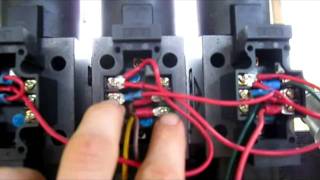
Basically,
the
top
I'll
point
to
this
on
the
top
top
wires
and
the
bottom
set
of
wires
the
corners
here
and
there
are
unused,
but
this
one
here,
these
ones
on
the
left
hand,
side
are
the
power
leads,
and
you
see
there
are
GL
wire
together,
because
the
connections
are
disconnected
on
a
negative
side.
So
here
the
top.
A
The
top
connection
is
the
brown
wire
that
happens
to
be
channel
two,
then
the
yellow
wire,
which
happens
to
be
channel
three
on
the
driver
board
so
top
and
bottom
electrical
connections
corresponding
to
quartz
a
and
B
and
the
convention.
They're,
being
let's
see
this,
I'm
reading
from
the
new
wiki,
the
electrical
connections
on
the
sauna
is
such
that
such
that
the
common
connection
is
removed
from
between
the
two
pins
on
the
bottom
right,
one
is
valve
arrived.
A
There
was
a
connection
between
these
two
pins
this
one
and
that
one
now
that's
not
used
in
our
case,
for
whatever
reasons
I
particularly
don't
understand,
that
I
mean
they
want
to
be
connected
because
they're
controlled
individually,
so
I
disconnected
that
and
that
works
now.
The
upper
electrical
connection
happens
to
open
up
port.
A
Let's
see
port
B
and
a
bottom
electrical
connection
opens
up
port
a
the
ports
are
labeled
on
top
of
the
aluminum
body,
as
I
mentioned,
as
I
showed,
and
one
can
actually
test,
which
is
which,
by
activating
either
port
and
blowing
through
the
valve,
to
determine
which
port
is
open.
So
on
the
sensors.
The
main
cylinder
sensor
is
analog,
channel,
0
or
digital
14
and
Arduino.
A
The
secondary
cylinder
is
on
channel
analog
one
or
digital
15,
so
I
see
the
show
the
video
for
this
operating,
but
for
now
I'll
just
quit
at
the
fact
that
this
table
here
just
look
at
the
table
and
you
have
the
driver,
pins,
solid
connection,
we're
like,
for
example,
top
connection
of
solenoid
to
bottom
connection
of
saw
92.
That
tells
the
Arduino
channels
which
are
found
within
the
code.
So
we
can
actually
understand
the
code.
A
The
motion
corresponding
is
left
and
right
upon
activation
and
a
sonic
port
wiring
is
that
port
B
goes
to
the
bottom
of
drawer
cylinder
port.
Eight
a
goes
to
the
top
of
drawer
cylinder.
Now.
Does
that
check
out
the
sport
be
go
to
the
bottom
of
jar,
cylinder
yeah,
we've
seen
that
this
is
poured
be
here
this
one
here,
port
B
goes
to
the
bottom
of
the
cylinder
port
a
goes
to
the
top,
so
that's
the
wiring
convection
convention
for
the
secondary
cylinder
explained.
So
you
can
understand
how
to
wire
this
in
case.