►
From YouTube: OSE Dev Team Meeting - Oct 31, 2017
Description
See meeting notes at http://opensourceecology.org/wiki/Development_Team_Log#Tue_Oct_31.2C_2017
----
What you see here at Open Source Ecology is an ambitious program based on a volunteer effort. To help us reach the goals - please consider joining as an OSE Developer in 2017-
http://opensourceecology.org/wiki/OSE_Developers
Take a minute to subscribe to our email newsletter (updates, workshops, etc): http://bit.ly/1LtcM44
A
B
A
A
Well,
that's
essentially
Lex
and
Josh,
who
were
here,
and
they
were
definitely
counting
these
hours
as
contributions
to
their
development
time,
which
is
during
the
workshop
they
were
here
so
we've
got
about,
I
mean
that
is
over
200
close
to
300
hours.
So,
like
10,
you
know
eight
seven,
eight
people
equivalent
almost,
but
that's
good,
that's
good!
We
see.
If
you
look
at
the
historical
graph
of
here,
you
can
see
that,
like
the
first
spike
on
May
1st,
that
was
actually
when
we
had
the
first
3d
printer
workshop.
A
So
every
time
during
a
workshop
time,
we
have
either
like
a
lot
of
preparation
on
site,
or
you
know,
a
spike
of
effort
to
get
the
documentation
or
just
that
people
from
the
team
participate
during
the
build
and
spike
up
those
hours.
So
that's
pretty
good
good
good.
Last
week,
so
I'm
gonna
just
dive
into
just
the
product
review
of
what
what
we
have
done
and
the
issues
that
we
have
encountered.
A
I'm
gonna
refer
to
the
the
micro
truck
CAD
to
look
at
some
of
the
details
that
we
have
changed,
because
there
were
definitely
a
few
changes
that
we
had
to
make
and
altogether
the
time
stretched
to
being
able
to
build.
Only
the
micro
tractor.
There
were
definitely
a
few
issues
that
we
encountered
things
where
the
CAD
was
just
didn't,
do
it
for
us
and
we
had
to
redo
what
we
did.
A
You
can
effectively
say
we
built
two
tractors,
but
it
ended
up
as
one
tractor
because
a
lot
of
parts
we
just
ended
up
redoing
for
various
reasons.
For
reasons
like
well,
it's
an
experimental
workshop.
Some
of
the
CAD
wasn't
correct.
In
complete
instructionals
lack
of
torch
table
I
mean
a
torch
table
with
a
nailed.
A
All
the
while
torch
table
plus
correct
design
would
have
nailed
all
the
issues,
but
all
together,
a
majorly,
successful,
build
I,
put
out
the
review
form
for
people,
and
most
people
gave
a
five-star
review
to
this
to
this
workshop,
which
is
great
so
we
got
probably
like
4.5
or
so
on.
A
review
from
about
10
people
who
have
provided
feedback.
I
actually
had
people
provide
feedback
like
right
in
the
last
days
review
session.
So
that
was
good.
So
quick,
quick
walk-through,
you
see
the
the
bucket
toothed
bar
separable
toothed
bar
built
tractor,
driven.
A
We
added
a
flow
control
valve
to
drive
the
tractor
slowly.
The
tractor
did
end
up
spinning
in
circles
as
in.
If
you
turn
one
level
lever
forward
and
the
other
in
Reverse,
you
can
spin
it
in
a
circle,
which
means
that
you
have
ample
traction
upon
the
tracks.
The
bucket
I
mean
just
amazing,
I
mean
quite
a
highlight
and
I'll
actually
zoom
in
on
a
detail,
but
we've
got
the
toothed
bar
we've
got
the
nice
geometry.
You've
got
the
Bobcat
standard
on
the
back.
A
We
even
attached
a
little
hook
on
the
front,
a
utility
hook
right
there.
You
see,
that's
that's
very
useful
for
pulling
chain
or
whatever
you
have
so
that
was
that
was
quite
nice.
We
put
a
supporting
crossbar.
We
just
ended
up
using
a
2x2
tube
the
arms.
You
see
we
did
not
kind
of
cover
them.
On
top
it
turned
out
the
geometry
as
it
was.
We
had
to
extend
actual
connection
points
up
to
the
the
top
of
the
arms.
A
Simply
because
things
didn't
fit,
I
mean
you
know
the
CAD
yeah
I
mean,
for
whatever
reasons
the
main
I
think.
One
of
the
main
reasons
was
that
the
tight
space
between
the
fittings
of
the
cylinders
and
just
a
geometrical,
yeah
I,
mean
I,
can't
really
tell
I
mean
we
kind
of
had
the
correct
dimensions
within
CAD
for
the
length
of
the
cylinders
as
far
as
I
knew,
but
we
ended
up
welding.
A
These
triangles,
which
were
4.5
inches
high
onto
the
top
of
the
arms
to
support
to
have
the
support
points
for
both
the
cylinders
and
the
first
cylinder.
We
mounted
it
on
a
yeah
on
the
bar
on
the
cross
bar
here
and
everything
else,
so
more
review
the
thing
that
pretty
much
killed
us
was
actually
the
the
motors
what
we
ended
up
doing
and
I'm
gonna
go
into
the
CAD
to
show
you
to
walk
through
this.
A
Okay,
so
let's
take
a
look
at
this,
because
this
is
this
is
a
good
chance
to
review
everything
that
that
happened.
We
thought
was
gonna
what
we
thought
we
were
gonna
see
in
in
reality.
That
didn't
happen,
but
the
thing
that
so,
let's
start
with
the
motors
so
turns
out,
the
motors
are
I,
mean
they're
bigger
than
this,
that
that
pancake
there
turns
out
it's
a
little
wider,
and
what
happened
was
that
the
motors
stuck
out
so
far
that
we
just
lost
all
the
length.
A
So
when
we
ended
up
doing
is
take
this
vertical
and
actually
we
we
grant,
we
torched
it
off
after
we
built
it,
because
we
could
find
out
only
after
the
reality
has
shown
itself.
So
he
took
the
vertical
and
we
torched
it
and
moved
at
two
inches
in
inside
the
frame,
and
that
gave
us
enough
rooms
such
that
the
motor
itself,
which
was
wider
than
in
a
cat
here
wider,
as
in
its
length,
was
wider.
A
We
pretty
much
inset
the
motor
into
the
frame
such
that
we
have
enough
room,
so
we
still
retain
a
42
inch
width
of
the
tractor.
Now
we
could
have
just
left
it
exactly,
as
is,
we
would
have
ended
up
with
I
think
the
number
I
mean
the
number
was
small.
We
would
have
ended
up
with
44,
but
we
said:
okay,
let's
really
nail
this
issue,
because
it's
something
that
we
would
want
to
solve
in
the
future.
So
he
said:
okay,
let's
solve
it
right
now.
A
A
A
The
little
bolts
that
are
here
that
are
not
shown,
and
it
was
just
marginal.
It
was
like
a
quarter
inch.
You
know
quarter
inch
of
interference,
but
we
had
to
completely
grind
down
the
sprocket
redo
it
and
mount
it
once
again
a
little
farther
out,
but
because
we
had
to
mount
it
farther
out
to
avoid
the
bolt
conflicts,
the
the
just
a
spatial
track
hitting
the
motor
conflicts.
We
had
to
then
end
up
torching
as
I
mentioned
the
vertical,
so
that
the
motor
would
still
allow
us
the
42
inch
width,
so
that
was
like
wow.
A
That's
I
mean
that's
like
you
can
think
about
how
much
effort
that
took
that
probably
much
pretty
much
ate
up
a
whole
day
of
effort,
because
you
know
everyone
else
was
bottle
necked.
At
that
point
we
couldn't
get
that
machine
right,
but
we
did
get
it
running
as
far
as
the
drive
system
by
Monday
morning,
which
was
yesterday
and
yesterday
we
also
finished
the
arms
and
everything
else
and
a
quick-connect,
but
that
was
a
major
effort.
Now
we
did
torch
the
major,
so
yeah
I
mean
successful.
A
What
we
have
ended
up
showing
is
that
we
can
do
the
actual
manual
torching
of
this
very
successfully
I
mean
so
so
are
people
at
the
workshop
were
novices.
We
taught
them
basics
of
how
to
torch,
Lexx,
actually
torched
out
most
of
the
sprockets
by
hand,
and
they
worked
perfectly
I
mean
they
weren't
super
pretty
or
super.
You
know
super
precise,
they
might
have
been
like
within
1/8
inch
or
you
know,
eighth
inch
plus/minus
on
the
the
critical
parts
being
the
round
parts
with
actual
rollers
of
the
chain
rest.
But
it
worked
right.
A
I
mean
the
the
figure
of
Merit.
There
is,
does
the
track
skip?
Does
it
drive
yes
and
rove
and
it
did
not
skip?
It
was
perfect.
So
we
have
learned
during
this
build
that
simply
having
a
torch,
a
welder
and
a
grinder
would
be
sufficient
to
make
this
entire
machine,
which
is
a
great
proof
of
concept,
because
we've
shown
that
you
don't
don't
need
a
torch
table
to
do
it
now
it
takes
longer
to
do
it.
A
So
if
you
have
access
to
the
bought
parts
or
the
engine,
you
know
we
buy
the
engine,
also
the
engine
there
we
made
everything
else
we
buy.
We
actually
bought
the
Bobcat
and
fitted
parts
both
of
them
the
male
and
the
female,
and
this
geometry
here
is
almost
almost
quite.
What
we
ended
up
doing
is
with
the
the
quick
attach
standard.
A
This
plate
actually
appears
to
be
wider
than
in
reality,
so
we
can
change
that.
But
anyway,
that's
that's.
Some
of
the
main
issues
we
encountered
the
motor
mounting,
which
totally
killed
us.
But
after
that
you
know,
team
was
really
good.
Everyone
was
working
together
supporting
each
other.
A
lot
of
learning
happening
bucket
I
mean
turned
out
exactly
as
we
have
here.
A
The
only
thing
that
I
mean,
but
once
again
as
I
mentioned,
we
redid
a
lot
of
things,
for
example
this
tooth
here,
it's
very
important
that
it's
on
the
very
edge-
and
this
is
absolutely
correct.
So
whoever
did
that
they
put
the
teeth
at
tooth
in
about
two
inches,
which
is
that
really
help
hurts
the
performance
of
the
machine,
because
that
means
when
you're
digging
you're
gonna
be
like
just
digging
essentially
down
to
like
two
inches
narrower
on
each
side
and
over
time.
A
A
Well,
we
ended
up
using
here
we
did
end
up
using
the
single
block
we
ended
up
using
instead
of
a
bar.
We
decided
because
of
the
way
the
cylinder
was.
It
was
relatively
hard
to
make
a
weld
to
the
bottom
end
of
the
main
cylinder.
So
we
said:
okay,
let's
leave
that
cylinder
and
intact.
Let's
use
a
quarter
by
four
quarter
by
two
inch
square
tube
and
we
just
welded
a
a
round
tube
to
the
insights
of
the
Select
rope
in
cylinder
could
be
mounted
to
that.
A
What
else
the
dimensions
in
terms
of
lengthwise
were
perfect
on
a
power
cube,
I
mean
the
power
cube,
fit
right
in
nice
and
snug.
The.
What
we
found
out
also
is
with
the
bigger
cooler.
What
ended
up
happening
is
the
fan.
We
got
a
12
inch
fan
so
when
we
used
it
that
the
larger
cooler,
which
was
the
1260
we
used,
the
1260
I,
believe
it
was
to
actually
12
68
Hayden
cooler,
the
fan
underneath
the
cooler
ended
up
hitting
the
tank.
A
So
we
we
used
a
smaller
fan,
which
was
an
8
inch
diameter
fan,
but
then
we
actually
found
out
that
there
were
further
conflicts.
It
was
really
tight
for
these
fittings
here,
both
the
in
and
out,
because
the
the
cooler
is
wider
than
shown
here.
It
was
somewhat
tight,
so
we
ended
up
putting
the
cooler
and
the
fan
actually
on
top
of
the
grate,
which
means
it's
not
really
protected
from
the
elements
or
from
stuff
falling
on
it.
A
We
so
one
of
our
guys
here
welded
one
of
the
more
experienced
guys
who
did
have
experience
with
welding
and
then
we
epoxy
did.
We
ended
up
with
one
leak
hall,
which
we
then
welded
up
round
down
the
epoxy
and
welded
it
up.
It
smells
when
you
burn
it
again
with
it
with
a
welder
and
we
fixed
it
the
first
time
around.
So
the
the
hydraulic
tank
was
relatively
painless.
A
We
did
a
major
design
change
on
them
on
raising
mechanism.
So
if
you
look
at
this,
you
see
that
there's
these
sleeves
that
go
up
and
down
the
arm
of
the
vertical
arm
supports
what
we
ended
up
doing.
One
change
was,
we
ended
up
using
two
bolts
instead
of
one
and
in
retrospect,
probably
one
would
have
been
good
enough,
but
we
kind
of
said.
Okay,
let's
do
two,
so
that's
more
evenly
supported,
but
the
other
thing
was
instead
of
using
the
sleeves
here.
A
A
So
that
means
the
bolt
here
was
was
hidden,
so
we
torched
out
a
hole
for
the
two
holes
for
the
bolts
too,
so
we
can
get
get
at
them
intentionally
and
when
we
did
that
we
found
it
was
so
difficult
to
tension
them,
because
he
can.
You
know
he
can
only
move
the
wrench
back
and
forth
so
much
with
it
too,
two
bolts
that
we
ended
up
welding
another
plate
on
the
bottom
of
the
tensioner,
such
that
the
nut
is
exposed
on
the
outside.
A
So
you
can
actually
get
much
more
of
a
better
wrench
hold
on
it,
which
saved
us
time.
So
we
ended
up
modifying
this
quite
a
bit.
What
we
ended
up
doing
is
when
this
plate
the
front
plate
ended
here.
The
motor
mount
was
just
another
plate
going
to
the
motor.
We
actually
removed
this
back
plate
here
and
allow
the
motor
to
pretty
much
bump
against
or
touch
against
this
vertical.
We
were
just
pretty
much
thinking
of
what's
the
simplest
way
to
do
after
we
got
into
the
crisis
of
this
stuff.
A
Until
this
side,
there
so
part
count
reduction
from
ten
to
four
which
wasn't
obvious
until
we
start
to
build
it,
and
we
say
whenever
you
build
it,
you
say:
okay,
you
got
this
cut
list
and
you
see
you
know,
that's
a
lot
of
cutting
and
then
you
immediately
start
thinking.
Okay,
this
has
got
to
be
simpler.
We
don't
I
mean
we
got
all
these
pieces
that
you
have
to
mark
and
then
cut
on
the
ironworker.
So
we
definitely
questioned
at
that
time,
which
probably
we
wouldn't
have.
A
If
we
had
a
CNC
torsion,
we
would
have
just
said:
okay,
we're
cutting
that
out
and
then
welding
it
together.
So
I
do
think
the
simplification
is
worth
it
and
definitely
you
wanted
the
accessible
nut
there
and
this
whole
mechanism.
It
worked
great
I,
mean
1/10,
the
tracks,
tension
perfectly
and
all
that
that
was
good.
Ok,
another
design
change.
Here
we
have
the
clamp
on
the
outside
here
and
we
don't
show
the
shaft
here,
but
what
we
ended
up
doing
was
torching
out
the
big
three
inch
holes.
A
We
put
a
the
three-inch,
do
M
of
the
precise
tubing
material
inside
that
hole,
and
then
we
we
just
one
inch
of
it.
So
here
it's
we
have
1/2
inch
thickness
here
right
is
that
half
inch
Oh
actually
we're
showing
we're
showing
one
inch
arms.
You
know,
that's,
that's!
That's
gonna
be
half
inch
here.
We
used
half
inch
material
there
so
for
that
bushing
for
the
shaft
to
the
bushing,
which
is
welded
to
the
arms
there.
A
That
bushing
was
only
one
inch
wide,
so
he
could
weld
that
in
without
you
know,
without
taking
up
that
space
and
what
that
allowed
us
to
do
was
to
use
a
single
clamp
not
on
the
outside,
but
on
the
inside.
So
he
took
we
actually
torched.
We
had
a
bunch
of
these
clamps,
so
we
torch
them
into
halves,
which
so
we
have
one
bolt
on
each
side.
A
We
put
the
clamp
on
the
inside
right
up
next
to
the
bushing,
and
we
did
that
on
each
side,
so
those
small
clamps
inside
this
area
were
sufficient
to
to
clamp
down
the
whole
arm
set,
which
was
good.
So
we
completely
redid
this
mounting
here.
Yeah
I
mean
here
this
looks
good,
but
it
turned
out.
I
mean
that
space
there
was
pretty
tight,
yeah
I
mean
the
CAD
cam.
A
Just
you
know
just
little
things
like
the
fittings
like
the
fitting
here
had
to
go
up
because
we
didn't
want
it
to
go
down
to
the
tracks,
so
various
just
detail,
issues
of
all
the
fittings
and
the
geometry,
and
somewhere
like
these,
we
can
read.
You
know,
take
a
look
at
again
at
whether
the
verify
whether
the
cylinder
specs
we
have
here
are
correct,
but
here
like,
for
example,
that
width
I
actually
ended
up
getting
the
bigger
cylinder
with
the
one
inch
shaft,
oh
yeah,
so
that's
different
than
in
the
cat
here
yeah.
A
Naturally,
we
have
to
update
that
and
see
that
see
whether
in
the
CAD,
we
can
actually
see
those
interferences
that
we
were
talking
about
why
it
wouldn't
fit,
but
which
means
the
answer
is
probably
yeah.
Just
just
to
rework
see
is
you
know,
evaluate
that
update
the
CAD
to
what
we
have
exactly
so
everyone
can
look
in
real
life.
It
would
be
very
nice
for
me
to
then
just
do
some
more
documentation
and
exactly
the
Assam
has
built
so
so
take
a
picture
of
all
the
details
that
have
been
changed.
A
A
Don't
really
need
it
at
this
scale
of
the
machine.
It's
actually
an
artefact
from
the
former
frames,
but
this
middle
piece
we
took
it
out
and
what
that
allowed
us
to
do
is
the
clamp.
So,
yes,
with
the
clamps,
we
modified
their
location
as
well,
so
the
plates
that
we
had.
We
actually
had
these
wheel
mount
plates
for
these
shafts
from
the
the
tractor
of
2015
ie,
the
big
tractor,
the
the
one
that
I
used
to
do
the
keyline
ploughing
and
nut
planting
of
the
20
acres.
A
We
had
those
plates,
so
we
reused
them,
but,
however,
the
and
those
plates
the
shaft
was
right
up
to
the
to
the
metal.
We
didn't
have
that
half
inch
space
or
any
space
for
the
the
collar
here.
So
what
we
did
is
we
took
the
collar
and
we
put
it
right
on
the
inside
that
edge
there.
So
we
put
the
collar
against
that
faith
face
such
that
only
the
half
inch
of
the
collar
was
grabbing,
but
that's
fine
and
there
we
used.
A
We
had
one
bolt
clamps
one
I
mean
a
pair
of
bolt
clamps,
not
triple
just
a
single
clamp.
That
was
enough
and
besides
the
six
inch
ones,
because
that
space
is
exactly
12.
It
fit
fit
because
it's
just
a
little
too,
not
too
narrow
for
them
to
fit
and
a
one
inch
bolt
clamps
they're,
very,
very
strong.
They
have
three
3/4
inch
bolt
holes
and
that's
1/2
inch
material
that
clamps
around
the
shaft.
So
not
a
problem
there,
the
tracks
we
did
exactly
as
in
this
picture.
So
that's
all
good.
A
The
idlers
are
pretty
much
exactly
as
built
the
the
width
we
were
aiming
for
42
inches
and
what
did
we
get
exactly
42
inches?
So
we
ended
up
doing
exactly
what
we
have
in
a
CAD.
As
far
as
the
overall
width-
let's
see
do
it
are
the
tracks
here:
10,
inches
or
9
inches.
Let's
see
yeah,
oh
actually,
here
they're
9
inches.
We
we're
using
10
inch
tracks,
and
that
means
we
had
a
little
less
gap
there.
A
We
didn't
end
up
cutting
our
tracks
any
like
from
the
10
inches
that
they
are
already
are.
That
worked
all
togethers,
but
even
though
that
space
is
slightly
smaller,
not
a
problem,
let's
talk
about
the
loader
loader
arms
and
let's
wrap
up
the
this
arm
support.
So
we
use
two
of
these
arm
supports
that
we
ended
up
using
them
about
about
these
are
here
shown,
are
what
are
they
about
6
inches?
We
we
ended
up
having
them
about
4
inches.
We
cut
off
that
because
we
use
two
of
the
tensioner
threaded
rods.
A
A
Loader
arms:
how
do
we
do
them
so
that
would
have
been
a
lot
of
cutting
by
hand,
so
we
actually
did
the
bot.
The
loader
arms
are
half
by
five
steel
on
this
part,
so
we
actually
ended
up
using
a
half
by
five
steel
piece,
a
straight
piece
that
you
already
you
just
cut
to
length
and
therefore
that
means
we
cut
it
off
right
there
at
this
knee
and
we
torched
out
the
rest.
A
So
that's
what
welding
does
so
once
we
had
four
of
the
arms
we
just
put
them
all
together
and
match
drilled
this
hole
and
that
at
that
point
we
mounted
the
the
arms
on
the
shafts
loosely
with
with
the
bushing,
with
a
slightly
oversized
hole.
I
mean
just
very
slightly
so
we
hung
the
the
first
loader
arm
to
get
the
geometry
here
and
then
we
figured
out
okay,
let's
use
this,
we
were
fumbling
with
what
to
use
there.
If
we
didn't
want
to
use
that
shaft,
so
we
ended
up
using
the
quarter
by
two.
A
We
first
welded
this
bottom
mount
of
the
main
cylinder
to
that
or
looked
at
where
that
has
to
be.
We
found
pretty
quickly
that
for
the
cylinders
to
fit
both
this
top
top
cylinder
and
the
other
one
had
to
be
above
in
order
not
to
conflict,
we
found
that
for
the
actual
quick
attack
plates,
since
they
do
not
the
ones
that
we
got
off
the
shelf
the
Bobcats
standard.
It
does
not
have
these
here
verticals,
so
we
had
to
weld
them.
A
We
had
to
find
out
where
exactly
they're
gonna
be
so
we
put
the
the
female
part
of
the
quick
attach
and
the
male
part
we
basically
locked
them
into
each
other.
We
put
it
in
front
of
the
tractor
and
found
out
exactly
where
those
mounting
tabs
have
to
be,
and
it
turned
out.
They
were
exactly
against
the
edge
of
the
male
quick
attach
part
and
that
worked
out
well,
so
we
were
able
to
weld
that
in
place
with
the
with
a
quick
attach
in
place
we
put
in
the
secondary
cylinder
to
find
a
world.
A
Where
does
that
hole
have
to
be
so?
We
ended
up
finding
out
that
yeah.
We
have
to
extend
it
just
like
the
main
cylinder
so
slowly
inch
by
inch.
We
we
put
in,
we
found
the
geometry
for
one
side.
We
we
built
that
at
those
extender
plates
we
mounted
the
cylinders
and
then
we
raised
the
arms
up
and
down
the
reach
is
very
nice.
It's
probably
what
we
have.
A
Let's
see,
loader,
if
you
look
at
that
what
it
is
fully.
Oh
I
took
it
out
of
the
raised
one
out,
but
yeah
it
has
a
nice
lift
height.
You
know,
just
just
like
we
predicted
in
the
CAD
to
about
you
know,
line
like
right
there,
it's
a
nice
dump,
height
and
all
together,
very
nice,
looking
machine
and
things
are
working
on
it.
So
I
look
forward
to
using
that
testing
it.
A
So
far,
we've
put
in
a
flow
control
valve
to
control
the
speed,
and
when
we
did
the
test
run,
we
first
started
by
a
straight
single
valve
to
spool
valve.
The
thing
was
fast
Wow.
It
is
really
fast
like
4.5
miles
per
hour,
I
mean
that
thing
just
takes
right
off
and
it's
pretty
dangerous.
So
we
put
on
a
flow
control
valve
to
slow
down
the
speed
of
them.
A
The
wheels
when
you're
out
in
an
open
I
mean
we
start
this
in
the
workshop,
but
when
you're
out
in
the
open,
you
can
do
that
fast
speed
for
travel,
but
in
general,
if
you're
not
paying
attention
you
can.
If
you're
and
you're
standing
right
behind
the
tractor,
it's
pretty
dangerous,
because
the
thing
actually
moves
quite
fast
so
definitely
want
to
be
standing
on
a
platform
or
reduce
the
speed.
So
we
did
the
flow
control
valve
to
reduce
the
speed
and
that
way
we
could
do
what
you
see.
A
If
you
look
at
the
OSC
workshops
face
book
page,
you
can
see
some
of
the
initial
drive
tests
on.
Oh,
yes,
I,
just
posted
that
post
of
the
tractor
on
the
OSC
workshops.
Facebook
page
this.
This
picture
you
scroll
down
a
few
you'll,
see
some
of
the
videos
of
the
initial
drive,
as
we
were
working
that
by
Lex
at
some
of
the
build
pictures,
good
stuff,
yeah,
really
good,
so
continuing
that
that
that's
where
we
are
in
a
tractor.
So
the
next
priorities
are
to
refine
us.
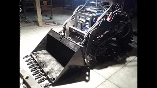
A
What
we
want
to
do
still
I
mean
man
this
this
bucket,
with
aggressive
teeth
and
an
attraction
that
machine
looks
so
solid
and
the
geometry
of
it
is
very
nice
and
tight.
So
we
were
all
really
pleased
on
the
overall
outcome,
and
this
is
the
machine
here:
you're,
basically
curling
the
bucket
downwards,
it's
its
farthest
and
it's
downward
position,
but
yeah,
of
course,
I
mean
the
machine.
Just
lifts
itself
right
up.
A
Yeah
I
mean
there's
a
lot
of
thousands
of
pounds
of
force
there
and
don't
know
exactly
how
much.
But
that's
that's
how
it
looks
right
now,
very
impressive.
It
looks
very
streamlined,
as
in
like
yeah,
just
kind
of
like
this
slant
going
up
the
single
power
cube
there.
We
did
not
do
the
second
power
cube
and
I.
A
So
that's
good
one
more
note
and
the
tooth
bar
is
removable.
We
put
you
see
those
bolts
there,
so
we
can
use
either
the
smooth
bucket
or
the
aggressive
digging
bucket.
The
teeth
are
sharpened.
This
is
the
same.
Open-Source
tooth
bar
as
I
did
first
around
2008.
That
design
is
good,
so
we're
ready
for
some
good
action
here,
so
immediate
applications
would
be
to
also
do
the
trencher,
the
vibratory
trencher
that
Josh
was
working
on.
We
can
implement
that
pretty
easily
to
burry
a
bunch
of
cable
and
do
some
work.
Probably
some.
A
You
know
erosion,
control
stuff
with
this
for
some
testing
and
other
general
utility
tasks
such
as
going
into
the
forest
and
getting
out
logs
and
and
firewood
things
like
that,
we
did
do
the
remote
control
box,
I,
actually
I,
don't
think
I
have
a
picture
in
here.
So
the
remote
control
box
was
the
Arduino.
So
just
just
moving
on
to
the
next
next
item
here
remote
controller,
a
box
with
an
Arduino
and
an
xB
wireless
or
remote
control,
radio
frequency.
A
So
one
box
was
the
controller
which
talks
to
through
the
wireless
to
the
second
controller,
the
little
controller
box
inside
an
electric
enclosure
which
raat
rests
on
the
tractor.
So
you
can.
You
can
move
this
remotely
so
basically
the
buttons
you
hit
the
buttons
on
your
the
handheld
controller,
and
then
you
can
see
that
the
same
solenoids
they're,
activating
the
the
sunlight
valves.
A
We
did
not
install
the
electric
solenoid
valves,
but
in
principle
you've
got
the
when
you
press
a
button
on
one
box.
The
same
same
solenoid
or
relay
opens
up
on
the
second
box.
So
basically
you
can
do
either
like
you
can
plug
in
the
the
solenoids
directly
into
the
first
box,
or
you
have
a
full
remote
control
mode
where
you
plug
in
the
tractor
to
the
second
box,
so
you
can
operate
either
one
or
the
other
or
actually
both
I.
A
Think
when
you
turn
on
both
remote
control
of
manual
control,
you
can
plug
in
the
tractor
to
the
box
directly
the
manual
manual
version
of
the
remote
control
or
plug
in
with
the
wire
to
the
receiving
box.
So
it's
basically
two
control
boxes.
One
is
the
one
you
hold
in
your
hand
and
the
other
one
is
the
one
that
rides
on
the
tractor.
So
that's
cool,
definitely
worth
doing
like
say,
say:
you're
doing
some
work
with
a
tractor
where
you
know
you're,
you
know
you're
knocking
down
trees
and
it's
dangerous
yeah.
A
A
So
that's
that's
pretty
much
the
report
from
the
weekend
so
overall,
very
exciting.
Last
night
I
mean
to
put
on
the
loader
arms
and
just
finish
it
off
of
it
was
up
there
like
2
a.m.
actually
last
night,
because
yeah
everything
took
a
lot
of
time
and
all
that
here
we
have
the
quick
couplers.
Everything
is
quick,
coupled
right
now,
etc.
The
the
levers,
the
quick
attach
works,
beautifully
I
mean
you
you
take
out.
You
know
turn
that
levers
up.
The
bucket
comes
off,
and
things
like
that,
so
very
nice
and
right
now
it's
machine.
A
A
So
so
we
do
want
to
continue
on
the
tractor
work
and
probably
do
the
update
the
CAD
on
a
micro
track,
so
I
can
go
down
there
and
actually
take
some
measurements
and
so
forth
so
that
we
can
update
this
cat,
but
I
mean
this
is
really
good.
I
mean
in
fact
already.
Somebody
has
emailed
me
pointing
to
the
workshop
and
and
asked
me:
how
much
are
you
charging
for
this
tractor?
A
A
So
we
definitely
want
to
take
this
to
do
full
product
release
pretty
soon
so
the
promise
is
being
delivered.
I
mean
this.
This
is
pretty
high
performance.
Let's
talk
about
the
big
tractor,
which
we
want
to
continue
so
guys
if
you
want
to
maybe
ask
some
questions
or
where
we
are
on
that.
So
the
priorities
at
this
point
would
be
to
finalize
this.
This
cat
here
we've
got
the
big
tractor.
What
I'm
gonna
be
doing
back
here
so
as
I
regroup
would
be
to
go
back
to
the
torch
table
and
then
any
next
build.
A
We
do.
We
want
to
pretty
much
relax
until
that
torch
table
is
up
and
running,
so
we
can
be
cutting
all
this
steel
and
so
forth.
So
there's
that
there's
also
the
wrapping
up
things
on
a
3d
printer,
where
we
want
to
do
the
next
iteration
of
the
extruder
and
if
you
guys
have
seen
the
latest
developments
on
the
Prusa
open-source
3d
printer.
There
are
some
features
there
that
we
want
to
incorporate,
but
we
don't
have
to
worry
about
that
for
now,
but
it's
very
impressive.
A
The
open-source
Prusa
printer
right
now
has
the
capacity
where,
for
example,
you
bump
the
head
and
you
move
it
by
accident,
the
printer.
The
controller
actually
understands
because
of
the
feedback
from
the
stepper
motors,
where
you
moved
it
and
it
moves
it
back
into
position.
I
mean
that
is
amazing.
So
the
feedback
on
the
level
of
the
actual
controller,
where
the
the
printer
itself
knows
where
it's
at
so
it
has
removed
the
end,
stops
man.
A
That
I
mean
that's
just
amazing,
so
you
don't
even
need
end
stops
because
the
printer
has
feedback
built
into
the
actual
controller.
That's
something
very
worthwhile,
but
we
don't
have
to
worry
about
that.
Yet
we
are
next
step
on
the
printer
is
to
do
exactly
what
we
have
with
a
12
inch
bed
printer
and
just
refined
the
extruder
head.
So
it's
really
robust,
like
we
so
Roberto
who's
gonna
ask
you:
did
the
printer
arrive
to
where
you
are?
Oh.
C
A
Yet,
okay,
so,
but
that
should
be
there
any
day.
It
said
six
to
ten
days
from,
and
that
was
over
two
weeks
ago
or
something
like
that
yeah.
So
we're
close
to
to
getting
there
that's
good.
But
those
are
the
three
main
things
right
now.
I
can
afford
I
mean
for
there's
the
tractor,
the
torch
table,
the
micro
tractor
and
the
printer.
Those
are
very
active
projects
and
Matt
joder
from
the
robotic
operating
system.
Ross
agriculture,
org
he's
still
here
so
he's
still
actually
gonna
install
the
GPS
model,
he's
actually
traveling
to
st.
A
A
Guys
tell
me
some
of
the
questions
that
we
have
I
know.
We've
been
discussing
the
big
tractor
there's
some
some
main
considerations.
We
should
probably
take
some
notes
on
what
are
the
main
design
requirements
so
that,
because
there's
many
questions,
I
mean
right
now
we're
open
to,
since
we
don't
have
any
pressure
on
a
time
because
we're
trying
to
get
a
design
that
we
can
actually
build
out
for
the
workshop
and
I
do
believe.
A
If,
because
of
the
experience
that
everyone
on
our
team
during
the
workshop
got,
if
we
were
done
with
this
micro
track,
we
could
have
potentially
even
build
the
big
tractor
cuz.
It
would
be
much
easier.
We
didn't
have
any
of
those
tight
space
considerations
as
in
the
micro
track,
so
we
could
have
potentially
have
done
that
in
a
single
day.
But
right
now
we
have
the
open
ability
to
source
any
other
parts
that
we
need.
We
initially
said:
we've
got
thirty
six
inch
and
24
inch
cylinders.
We
can
do
whatever
cylinders
lengths.
A
D
A
Absolutely
and
yeah
give
me
a
day
or
two
to
do
that.
I've
got
to
pretty
much
catch
up
on
some
other
tasks,
because
on
the
home
front
here
over
the
last
week
we
have
installed
the
open-source
hydronic
stove
and
I
still
actually
have
to
do.
The
hydraulic
control
panel,
so
I'll
be
working
on
it
for
the
next
day
or
two
I
can
possibly
get
all
the
changes
dimensions.
I
mean
one.
A
We
can
look
at
the
basically
review
what
I
talked
about
in
the
last
50
minutes,
but
the
second
part
is
taking
detailed
picture
details
of
every
single
component
on
this
existing
tractor,
so
that
so
I
can
do
that.
But
hopefully
yeah
do
that.
That's
that's
a
good
priority
and
anyone
else
who
is
free
to
do
stuff.
A
We
want
to
go
right
to
the
prototyping
stage
and
that
and
I'm
there
I'm
thinking
it's
like
one
or
two
days
where
we
actually
build
the
whole
thing
and
I
I'm,
pretty
sure
we
can
do
that
because
we
have
all
the
parts
we've
got.
The
extra
experience
from
this
build
one
or
two
days
would
probably
be
enough
to
do
the
the
build
pending
good
preparation
having
some
of
the
fabrication,
drawings
and
everything
else,
but
as
I
mentioned,
I
don't
want
to
do
that
until
the
torch
table
is
in
place.
A
But
so
on
my
side
here,
the
high
priority
is
to
get
the
torch
table
operational.
So
we
can
actually
cut
the
parts
for
the
life
track,
whatever
we
need
their
so,
but
we
definitely
want
to
prepare,
make
the
room
make
the
setup.
The
the
work
basically
define
the
work
breakdown
for
both
projects,
since
they're
they're
active.
D
D
A
Yes,
so
Lex
and
Josh
are
fully
qualified
to
make
all
those
changes
since
they've
seen
it
here.
So
that
is
good.
We
can
definitely
get
them
on
this.
So
let's
actually
start
another
page
here.
So
one
is
life
track
requirements
and
second,
is
the
tasks
as
we
typically
do
the
task
list
being
specific
on
what
that
is.
So,
yes,
so
task
list
task,
one
also
its
update.
A
From
other
people
from
others
during
the
workshop,
there's
also
one
more
task,
and
that
is-
and
it's
not
you
know
not
not
really
critical,
but
we
have
a
full
time
lapse
of
every
single
day,
actually
posted
a
bunch
of
that
on
the
YouTube
channel
for
for
factory
farm
for
OSC.
Out
of
that,
you
can
look
at
the.
If
you're
aware
of
the
CAD,
you
can
see.
Okay,
people
are
working
on
specific
tasks.
You
can
actually
get
out
the
ergonomics
of
build,
how
much
time
it
took
to
do
certain
things.
A
That's
that's
doable
like,
for
example,
how
much
time
did
it
take
for
people
to
to
torch
out
the
sprockets
manually?
So
if
you've
got
a
keen
eye,
you
can
work
with
the
video
recording
the
time-lapse
in
which
one
minute
corresponds
to
one
hour
of
build
time.
So
that's
another
task
without
I,
wouldn't
prioritize
that
so
much
a
secondary
priority,
just
to
say
that
it
exists,
but
I'm
not
gonna
allocate
anyone
explicitly
to
that.
A
A
One
of
the
comments
that
came
out
during
the
workshop
was
Lex
who's,
offering
to
do
like
a
little
station
like
a
documentation
station
where
we
have
a
video
camera
on
it,
and
it's
a
mobile
station
that
you
can
roll
it
to
your
station
and
record
exactly
what
you're
doing
it
has
two
big
buttons
start
and
stop.
So
when
you
started
it
starts
recording
when,
when
you
hit
stop,
it
would
stop
recording
so
something
like
a
Raspberry
Pi
camera.
So
a
Raspberry
Pi
with
a
monitor,
very
simple
system
for
doing
documentation.
A
So
we
can
record,
like
you're
gonna,
have
these
mobile
stations
during
the
workshop
that,
if
you're
working
on
a
specific
part
take
one
of
these
stations
put
it
on
you
head
start
and
then
hit
stop.
So
you
get
both
the
actual,
build
detail
and
the
ability
to
take
the
time
data
out
of
it
from
there
from
the
time
lapse.
A
Recording
so
that's
gonna,
be
we're
looking
at
that
as
one
of
the
changes
to
improve
the
documentation
coming
out
of
this
with
this
workshop,
so
workshops
that
we
have
here
so
the
time
lapses
are
pretty
much
data
rich.
In
terms
of
time
time,
data,
okay,
so
update
micro
tract
CAD
work
on
life
track
CAD.
A
A
We
could
probably
send
out
a
a.split
special
documentation,
request
form
to
all
the
participants.
Saying
simply,
did
you
take
pictures
and
where
are
they
so
a
link
to,
for
example,
the
Facebook
or
whatever
they
put
on
a
Google
Drive
or
they
they
have
it
on
their
camera?
Ask
them
to
upload
it
and
send
a
link
to
the
video
and
stuff
like
that.
So
I'll
actually
write
that
down
right,
so
other
as-built
pictures.
So
then.
A
14
people
participate
in
this
workshop,
so
it
was
rather
small,
but
that's
part
of
the
reason
why
we
didn't
get
as
far
as
we
would
have
liked
on
the
big
tractor.
The
assumption
was
there
was
that
we
have
24
people
if
we
were
to
do
everything
I'm,
not
sure
that
was
clear
within
the
event
announcement.
But
if
we
do
an
ambitious
build
up
to
machines,
I
mean
you
need
to
do
any
more
than
12
people
to
do
that.
Okay,
so
life
track
at
let's,
let's
get
into
it
so
lat
next
is
so
CNC
torch.
A
I
I
mean
I'm
gonna
try
to
keep
to
the
promise
of
not
doing
any
build
without
the
torch
table.
Now
we
know
the
pain
and
glory
of
doing
an
on
torch
table
work
which
once
again
for
lower
resource
environments.
You
just
need
a
torch
welder
and
a
grinder,
so
cnc
torch
testing
finishing
the
the
torch
table,
as
is
the
solution
on
it,
may
be
as
simple
as
the
settings
on
a
stepper
driver
are
incorrect,
because,
but
there
are
some
movement
issues,
so
testing
finishing
others,
the
3d
printer
main
priority.
A
C
A
And
that's
a
good
way
to
to
have
you
actually
participate
and
get
familiar
with
everything
before
we
go
more
ambitious
and
and
actually
design
our
own,
and
it's
you'll
see
that
you
know.
Just
like
we
design
a
tractor,
it's
like
to
design
the
extruder
itself.
You
just
have
to
go
through
the
process,
and
but
at
that
point
we're
gonna
have
full
control
over
the
device.
A
Just
like,
for
example,
right
now,
with
a
micro
track,
I
mean
we
have
got
full
control
over
every
single
part
of
it
and
it's
completely
repairable,
transparent,
open,
doable
in
the
home
workshop.
If
you
like,
so
that's
the
3d
printer,
oh
good
news
from
the
so
remember,
I
was
talking
about
tech
for
trade.
They
and
I
had
a
conversation
with
them,
so
filament
maker
I
had
a
conversation
with
them
and
they
decided
to
go
to
be
fully
open
source.
A
So
that's
great
news:
I'm
gonna
have
a
conversation
with
them
in
the
next
few
days,
but
they
have
the
PE
T
extruder,
so
PET
plastic,
which
is
a
very
common,
very
widely
accessible
plastic
that
can
be
recycled
into
filament.
So
we're
gonna
look
at
the
helping
them
on
their
their
version.
I
think
we
want
to
definitely
finish
up
our
version
of
the
ABS
extruder
just
for
more
experience,
but
they
have
an
open
source
design.
That's
in
a
pretty
good
shape
that
they're.
Actually
you
know
they've
used
it
to
build
to
make
filament.
A
So
we
can
collaborate
with
them
to
see
what
what
what
is
there
to
do
that
they
actually
have
a
more
advanced
version
in
their
version
to
actually
have
a
water
bath.
It's
a
it's
pretty
much
like
the
next
step
up
in
extrusion
in
the
extrusion
world,
but
that's
good.
So
there's
the
linemen
and
there's
the
tech
portrayed
tech
portrayed
the
African
extruder
yep.
A
Those
are
the
kind
of
the
main
things
on
a
plate
here,
but
let's,
let's
get
right
into
the
the
tractor
requirements.
So
let's
go
through
that,
so
we
can
definitely
break
it
down
into
the
main
components
as
we
normally
do
and
we
want
to
go
through
what
are
the
main
requirements
for
each.
So
just
a
simple
diagram
here.
A
Main
consideration
is:
how
do
we
make
the
cab
tracks
and
arms
fit
together
and
and
then,
where
do
you
mount
all
the
cylinders
who
should
be
specific
on
what
those
requirements
are
so
the
vet?
There
were
various
questions
that
were
raised
through
this
process.
So
maybe,
let's,
let's
take
a
look
at
all
those
questions
and.
A
D
A
Yeah
I
are
you
reflect,
for
example,
that
yeah
okay?
So
let's,
let's
do
one
thing
at
a
time:
let's
go
through
the
mounting,
but
they're
related
to,
though,
because
how
you
mount
the
by
the
way
that
the
power
cube
the
master
power
cube,
has
gonna,
be
that
has
to
be
the
top
one,
because
otherwise
you
would
have
priming
problems.
A
A
Across
work,
well,
I
mean
what's
the
bow,
how
do
you
translate
to
a
requirement
has
to
have
structural
strength
and
it
cannot
move
side-to-side
so
cannot
move
side-to-side
can
move
up
and
down
I
mean
that's
obvious.
Can
move
up
and
down
pay
attention
to
easy
access
to
the
bolt
head
to
actually
do
the
tensioning?
The
good
thing
is
you
do
that
only
once
like
you
do
that
and
then
you
know,
your
track
should
be
good
for
a
long
time.
So
clear,
clean
access
to
the
bolt
for
tensioning
to
to
the
nut.
A
D
A
Yes?
Okay,
so
you
have
drawn
one
vert
that
if
you
mount
it
at
the
very
base
that
that
works
right
but
yeah
I
mean
that's
totally
acceptable
right.
So
that
means
you
get.
This
I
mean
look
at
how
high
you
get
you
get
to
the
tipping
point
of
the
bucket.
That's
I
mean
that's
pretty
high
and
it's
pretty
good.
Do
we
know?
Can
you
tell
me
the
distance
to
the
bottom
of
the
bucket
there.
A
The
cab-
let's
see
the
I'm
gonna,
take
some
measurements
here,
so
the
cab
itself.
Currently
we
have
it
at
53
inches,
so
like
four
feet
and
a
little
more,
almost
almost
60.
If
you
include
the
bottom
of
that,
so
it's
about
five
feet
and
that's
an
yeah
I
mean
that's
what
we
have
there
I
mean
that's
pretty
good.
A
D
D
A
Yes,
yep
80,
80,
inches
mm-hmm,
eighty
inches
there's
a
little
less
than
seven
feet.
I
mean
that
is
quite
good
for
high
loading,
yeah
yep,
that's
I
mean
that's
quite
good,
so
what
you
drew
there
is
actually
nice
and
what
we
care
about
is
the
cab
with
allows
the
operator
to
get
in
there.
Currently,
in
that,
drawing
there
we
have
cab
width
of
30
inches,
which
means
that
if
we
are
using
4x4
to
being
the
space
in
between
that
is
22.
D
A
A
B
A
So
so
the
number
one
requirement
is
determined
by
the
mounting
of
the
quick
attached
plate
right
and
are
we
assuming
so
for
the
quickens
for
the
Bobcats
standard?
We
can
make
different
assumptions
such
as
well.
The
requirement
is
no
more
than
45
inches
correct,
because
that's
as
wide
as
the
Bobcats
standard
plates
come
is
that
correct.
D
A
D
A
A
D
D
A
Okay,
yeah:
let's
not
worry
about
it!
For
now,
let's
get
clear
on
the
what
the
requirements
are,
so
so
we
have
to
take
all
that
we're
saying
here
and
make
some
design
requirement
decisions
based
on
which
design
requirements
are
the
most
important,
so
I
would
call
for
the
number
one
requirement
is
that
we
do
not
complicate
the
mounting
of
the
loader
arms
to
the
quick
attach,
in
other
words,
allow
it
to
be
the
same
width
and
only
upon
that
making
the
whole
situation
impossible.
A
We
have
the
a
certain
width
that
lines
up
with
a
bobcat
standard
as
as
is
off-the-shelf
right
pinning
into
the
outer
hulls
of
the
bobcat
standard
of
the
Bobcat
female
and
remaining
within
45
inches
of
of
that
and
I
see
in
the
current
CAD
actual
mounting
is
like
about
one
inch
away.
The
the
male
part
is
that
so
well,
it's
yeah.
Let's
take
that
measurement
there.
A
What
what
we
can
learn
from
this
build
is
exactly
what
the
off-the-shelf
quick
attach
looks
like
make
sure
that's
accurate,
both
here
and
then
the
micro
track.
But
what
is
wrong,
for
example?
Okay,
if
we
examine
what
we
have
currently
in
there,
we
have
a
if
we
have
a
31
wide
cab,
but
it
would
have
to
be
a
little
smaller
because
you
want
some
space
so
say
you
got
a
maximum
of
29.
So
say
you
leave
one
inch
space
between
the
cab
and
the
arms
going
up
and
down
so
say
you
got
29
inches.
A
Then
if
we
use
the
four
inch
tubing,
then
we
reduced
to
21
inches,
which
is
pretty
small.
One
thing
we
can
do
is
maybe
say
for
the
cab
we're
gonna
use
2
by
2
inch
2,
let's
say
so.
We
can
do
something
like
that
if
we
have
29
minus
4
at
that
point,
that's
25
I
mean
that's
a
small
me.
That's
pretty
small,
but
I
think
possibly
acceptable.
A
A
D
D
A
Okay,
hold
on
hold
on
right
there,
so
I
am
measuring
the
outer
arm
to
arm
distance
and
I'm
measuring
40
okay.
So
we
know
that
that
could
be.
You
know
if
the
width
is
45
and
where
we
got
just
a
little
bit,
but
that's
44.
So
we've
got
four
inches
right
there
that
we
can
expand.
The
arms
outwards
right.
A
Let's
see
what
we're
saying
here
is
that
the
cab
is
kind
of
like
the
the
relationship
between
the
cab
and
ability
to
mount
a
quick
attach
in
front
of
it,
where
you
can
still
have
enough
space
in
the
cab.
That's
one
major
consideration,
yeah.
What
you're,
showing
there
on
page
three
with
those
extenders.
D
C
D
A
Yet
don't
don't
bring
the
bucket
from
the
micro
track
in
because
we
know
that
if
we
have
the
Bobcat
standard,
that
bucket
will
fit,
because
right
now
that
actually
that
bucket?
Oh
yes,
so
I
mean
maybe
have
not
mentioned,
but
right
now,
in
a
picture
that
you
see,
you
see
how
the
Bobcat
standard
on
page
five
of
the
document,
the
the
female
part,
is
actually
sticking
out
a
couple
of
inches
and
we
left
it.
There.
A
D
A
A
Yeah
that
or
even
if
we
cut
it
off,
look
on
page
five,
we
cut
it
off
down
to
42
and
don'twell
decides
back
in.
You
can
still
grab
that
with
a
big
tractor,
correct
yeah
right,
so
don't
worry
about
it.
Let's
not
confuse
the
discussion
with
any
of
those
considerations.
Yet
so,
let's
look
at
the
baseline
facts.
We've
got
a
45
inch
wide
quick
attach.
A
A
A
So
I
just
drew
there
the
bottom
of
the
arm
and
then
we
need
the
other
piece.
Do
you
see
it?
We
need
another
piece
here
so
under
your
picture,
I'm
just
drawing
a
small
picture
of
that's
the
bottom
of
the
arm
and
what
we
have
there
on
top
of.
That
is
the
place
where
the
pin.
So
we
had
this
little
extender
and
in
that
extender
we
have
a
Hall
which
is
a
one
inch
hole
for
the
pin
okay.
So
we
have
that.
A
A
A
A
Yeah,
so
we're
not
worrying,
what's
on
top
what
the
female
part
is
yet
of
the
quick
attach.
So
let's
talk
about
the
male
quick
attach
part,
the
part
that's
on
the
loader
arms
such
that
we're
attaching
to
through
with
the
pens
so
we're
where
we're
at
the
connection
of
loader
arm
to
the
male
quick
attach
and
we
have
45
inches
of
width
available.
So
what
if
we
put
so
whatever
our
loader
arms
are,
we
can
mount
a
Tang
on
the
inside
part
of
the
loader
arm.
A
A
A
A
A
So
the
mounting
Tang
is
like
this:
here,
that's
the
Tang.
It's
got
the
hole,
it's
got
the
hole
in
it
wherever
that
hole
is
I
mean
it'll
be
towards
the
bottom.
There
does
that
make
sense.
So
that
way
we
can
have
the
most
space
available
to
support
a
cab
in
between
the
loader
arms
yeah.
So
that's
that's
to
start
with,
so
the
dimensions
here
are
45
wide.
C
A
A
The
curl
cylinder
would
be
somewhere
there.
Let's
say
you
know
cuz,
because
if
we're
remaining
within
the
the
bobcat
standard
quick
attach
so
but
then
the
curl
cylinders
how
people
do
that
sometimes
is
they
actually
make
a
mount
on
the
inside
of
the
loader
arms
and
that's
doable?
But
once
again,
that's
complications
unless
you
do
something
like
it's
a
complication.
Unless
you
do
something
like
a
big
shaft,
you
know
I
mean
there's
ways
to
address
it
right.
A
A
So
what
you
see
here
is
this
gets
complicated
right,
that's
the
bottom
line,
so
we
want
to
try
to
look
for
a
simple
solution,
so
we
want
to
you
want
to
try
to
do
what
we
did
in
in
micro
track,
which
is
beautiful.
So
if
you
look
at
page
six,
everything
is
behind
your
Bobcat
quick,
attach
right,
it's
sandwiched
in
between
where
the
mounting
is
easy
and
so
forth.
So,
typically,
what
people
have
is
the
loader
arm.
The
cylinders
are
right
in
front
of
it.
A
It's
easy
to
attach
them,
and
so
that's
the
curl
cylinder
and
the
main
cylinder
is
also
once
again
inline
with
the
loader.
So
it's
easy
to
attach
it
as
well.
Otherwise,
attaching
to
the
side
is
not
as
easy.
It's
done
a
lot
of
times
like
if
you
look
at
the
lot
of
the
Bobcats
and
their
cylinder
mounting
as
I
believe
on
the
inside.
Because
of
this
exact
issue.
D
D
D
A
D
D
B
B
C
A
Well,
these
are
all
related
issues
we
have
to
strip
this
to
requirements
like
the
number
one
question
is
to
clarify
this
discussion:
are
we
making
the
cab
a
module
or
are
we
not
making
it
a
module,
because
if
it's
a
module,
that
means
it's
completely
independent
outside
of
attachments
say
to
the
base?
If
we
put
the
loader
shaft
through
the
cab,
then
you
bottleneck
the
build
process.
A
So,
given
that
modularity
is
one
of
our
first
design
intents,
we
should
keep
them
separate.
Do
not
put
the
shaft
through
the
cab
so
that
you
can
have
the
frame
where
you
have
the
loader
arm.
Pivot
mounts
through
the
frame,
that's
what
we
started
with
and
I
would
say
until
we
get
to
a
catastrophic
point.
We
keep
that
requirement.
In
other
words,
in
the
slide
number
three,
we
had
the
cab.
A
Well,
we
missed
the
frame
right.
So,
let's,
let's,
let's
go
back
to
that
diagram,
so
there's
tracks
there's
you
can
stack
the
frame
here,
power
cubes,
but
what
this
diagram
means
is
that
each
part
is
independent,
connected
in
a
very
simple
way,
like
the
cab,
simply
bolts
onto
the
frame,
the
power
cubes.
Simply
like
rest
on
the
frame
etc,
so
the
frame,
if
it's
independent,
then
a
way
to
attach
the
interface
design
between
the
frame
and
arms,
is
that
pivot
shaft
with
the
holes
in
a
frame,
that's
acceptable.
A
So
you
can
work
on
the
arms
independently,
like
once,
you
figure
out
the
geometry,
you
can
build
those
arms
completely
independently
and
we
want
to
design
it
design
the
build
process
such
that
we
can
do
that
independently.
If
our
goal
is
transforming
manufacturing
by
social
production
and
words
that
we
can
build
this
in
a
weekend,
so.
A
A
We
didn't
have
any
people
like
that
this
time
around,
so
that
was
really
good,
but
we
want
to
design
a
social
process
into
this
and
therefore
an
intense
weekend.
Build
event
is
a
format
to
achieve
that.
So
we
keep
things
modular
and
we
want
to
say
that
the
arms
are
connected
to
the
frame,
so
I'm
gonna
make
that
explicit
here.
A
Until
further
notice,
until
we
find
this
is
catastrophic
for
some
reason,
but
let's
not
give
up
this
point
because
it's
an
important
one,
so
let's
mount
the
arms
to
the
frame
and
the
quick
attach
goes
to
the
arms.
The
cab
is
literally
like
the
cab
is
gonna,
be
complicated
because
inside
the
cab
you
have
all
the
hydraulic
controls
and
to
fit
those
hydraulic
controls.
That's
like
a
full-time
job
for
one
team,
so
we
can
say
like
I,
do
want
to
make
that
explicit
the
cab.
A
A
Okay,
so
you
want
to
enable
the
building
of
hydraulic
controls
pretty
independently,
and
then
you
can
simply
install
them
inside
the
cab.
But
this
all
requires
that
we're
clear
on
the
modularity
here.
So
we
can.
I
mean
I'll,
symbolically
speaking
out,
public
I,
draw
controls
separate
from
the
cab
but
they're
they're
going
in
the
cab.
A
So
we're
getting
more
more
explicit
here.
What
happens
here?
We
have
the
tensioner
that
we
did
not
address,
but
the
tensioner
is
related
only
to
the
frame
and,
let's
see
so,
let's
like
keep
spreading
this.
So
it's
clear,
tensioner,
that's
the
that's!
The
modular
breakdown
part
of
the
design
process,
so
you
got
the
tensioner
which
currently
and
we
can
renegotiate
some
of
these
connections,
but
we
got
to
be
very
clear
about
where
we
are
modular
for
the
purposes
of
the
build.
A
So
let
me
continue
adding
these
connections,
so
tensioner
connects
to
the
frame
and
the
frame,
but
also
that
the
tensioner
is
connected
to
the
drive.
Well,
the
tensioner,
you
can
say
tension.
The
tensioner
is
integrated
with
the
driver
that
the
motor
is
right
on
a
tensioner,
so
the
tensioner
driver
is
a
module
and
attention
or
driver
which
is
the
sprocket
address.
Let's
call
it
specifically
drive.
Sprocket
is
connected
to
the
tracks.
A
A
Connect
the
tracks
to
the
frame-
this
is
kind
of
interesting
here,
what
you're
seeing
the
emergence
of
a
kind
of
a
formal
analysis
of
modularity
inside
a
machine,
so
basically
it's
all
the
modules
and
which
are
the
existent
connections
and
which
do
not
exist.
So
this
diagram
actually
is
has
a
lot
of
information
in
it.
So
tracks
connected
to
idlers,
Plus
shaft,
which
is
the
idler
assembly
and
the
idlers
Plus
shafts
connect
to
the
frame.
A
But
this
is
it
that's
what
we
have
so
if
we
do
the
design,
we
have
to
be
consistent
with
it.
Otherwise
we
say
we
agree
on
a
different
connection
diagram,
but
this
if
you
analyze
it
allows
for
a
complete
parallel,
build.
You
can
build
a
quick,
attach
and
build
the
arms
independently
and
build
the
frame
independently
cab,
independently
hydraulic
controls,
independent
tensioner
and
drive
sprocket
independent
power
cubes
are
completely
independent.
We
know
that
idlers
and
shafts
are
completely
independent
and
so
are
the
trucks.
These
are
all
independent
teams
that
can
work
without
any
bottleneck.
A
A
You
can
drop
a
cop
like
many
of
those
constraints
and
we
can
define
those
constraints
and
that's
perhaps
like
I,
would
say
the
next
step.
Maybe
we
we
go
through
this
and
actually
you
know,
label
that
that's
constraint
number
one
and
we
say
the
cab
fits
between
the
arms.
You
know
there's
no
question
about
that.
That
always
happens
so
that
as
a
design
requirement.
A
A
For
example,
here
I
said
this
gets
complicated,
but
if
we
have
a,
for
example,
the
cross
bar,
where
we're
attaching
the
law,
we
can
use
that
cross
bar
to
attach
loader
arm
cylinders,
for
example,
so
that
maybe
maybe
we
can
do
this
exactly
as
we
have
here,
but
attach
the
cylinders
in
a
different,
the
curl
cylinders
in
a
different
way.
So
so
it's
up
to
us
to
do
that,
and
here
I
mean
this
mounting
tank
I
mean
I,
didn't
draw
this
entirely
correctly,
because
that
mounting
Tang
has
to
be
within.
A
A
D
D
D
On
the
outside,
as
long
as
the
arm
tangs
are
on
the
outside
of
those
plates,
if
we
don't
want
to
put
him
on
the
inside
and
they're
all
the
arms,
we're
just
gonna
have
to
narrow
the
cab
a
little
more
to
get
the
arms
well
yeah
or
I.
Guess
we
could
narrow
the
arms
and
the
tangs
could
go
on
one
side
of
the
plates
or
the
other
actually
yeah.
A
Right
some,
what
I'm
trying
to
show
here
is
that
the
tangs
can
be
like
either
in
the
middle
of
the
loader
arm,
or
it
can
be
like
on
the
inside
of
the
loader
arm.
As
long
as
that,
bottom
of
the
loader
arm
is
stiff,
that
you
can
mount
those
I
mean.
The
pin
plates
could,
for
example,
be
like
a
one-inch,
thick
steel
or
1.5
inch
thick
piece
of
steel.
A
A
Thick
steel
and
into
it
in
order
to
make
it
more
strongly,
can
weld
in
like
a
bushing,
that's
wider
than
one
inch.
If
one
inch
is
not
enough,
because
one
inch,
you
can
a
get
out
with
the
other
pin
with
a
lot
of
weight
on
it
going
against
it
all
the
time
the
one
inch
thick
steel
will
tend
to
it'll
just
get
ripped
after
enough
time.
So
we
wanted
to
reinforce
it
probably
with
something
like
a
bushing
inside
that
thick
steel.
So
if
you,
okay,
so
I
drew
the
tang
here.
A
So
I
think
that
yeah,
that
is,
you
know
it's
a
hole
that
goes
through
the
whole
thing,
but
it's
reinforced
by
another
piece
of
steel
that
can
be
like
this
very
thick
thick
tube,
like
do
em
to
being
or
even
xxx
H
heavy
wall
pipe.
That's
one-inch
pipe
that
actually
fits
a
1
inch,
shaft,
pretty
pretty
reliably,
which
is
actually
what
we
used
as
the
material
for
the
rollers
on
the
track.
So
that
meant
that
kind
of
material
like
a
very
thick
bush.
So
that's
a
potential
design.
A
A
A
So
this
this
would
be
welded
somehow
into
it.
Yeah
so
yeah
there's
complications,
but
what
I
see
here
is
that
we're
gonna
have
some
creative
work.
Doing
this
and
I
think
what
we
did
in
micro
track.
That
was
great
I
mean
that
that
worked
really
well
and
it
looks
very
attractive.
So
we
can
do
a
good
job
on
this
too,
so
yeah
yeah,
but
we
got
to
figure
it
out.
A
I
really
got
to
get
going,
so
maybe
we
can
communicate
still,
but
if
you
guys
want
to
go
back
into
the
page
number
three
life
track
requirements,
I
mean
keep
adding
stuff
in
there,
I
mean
I
think
for
the
cab.
We
really
want
to
have
like
24
inch.
I
mean
that's
only
two
feet:
yeah,
let's
stick
with
24
inch
between
the
vertical
bars
that
you
can
get
in
there.
D
A
A
We
do
not
have
any
of
that
material
with
the
hulls
already
like
the
four
by
four
tubing,
so
for
that
we
can
weld
it
up,
but
then,
as
far
as
the
attachment
of
all
the
hydraulics
and
every
other
component,
we
just
have
to
drill
more
holes
or
torch
more
holes
wherever
we
need
mounting
points.
So
that's
the
only
inconvenient
part,
but
we
could
also
consider
things
like
we're
hanging
we're
putting
in
more
tubing
members.
So
we
can
actually
hang
things
off
or
something
so
yeah.
A
We
can
figure
that
out,
but
the
advantage
of
the
four
by
four
inches
that
already
has
the
holes.
We
can
mount
anything
already
so
so
the
disadvantage
there
is
is
having
to
drill
holes
but
also
I
mean
just
like
we
have
the
4x4
tubing.
We
can
possibly
consider
now.
We
have
the
two
by
two
and
we
also
make
that
into
our
standard
box
beam
with
the
holes
I
mean
we
can
take
that
on
a
torch
table
and
make
that
as
a
standard
part.
A
It
would
be
quite
useful,
though
a
one-inch
hole
through
that
would
weaken
the
material
like
we
have
one
inch
holes
on
the
other
one
other
ones,
so
we're
primarily
using
one
inch,
bolts,
I'm
trying
to
really
reduce
as
much
as
possible
to
simply
one
inch
bolts
because
they're
very
strong
and
all
of
that.
So
if
you
do,
the
the
two
by
two
you'd
have
to
use
probably
smaller
than
to
one
inch
bolts,
but
3/4
probably
would
be
good
and
we
do
use
a
lot
of
3/4.
A
We
don't
use
so
much
of
half-inch
because
we're
you
know
we're
trying
to
pay
attention
to
like
really
serious
part
count
reduction.
So
we
we
do
use
a
lot
of
one
inch.
3/4
inch,
I
mean
half
inch
is
very,
very
common
and
we
might
have
to
just
use
that
for
the
thinner
frames
and-
and
of
course
the
thinner
frame
does
not
have
as
much
strength.
So
you
couldn't
like
it's
not
a
structural,
it's
not
gonna
be
a
structural
as
the
as
the
4x4
I
mean
the
4x4.
Probably
a
tree
can
fall
fall.
A
Onion,
nothing
would
happen
like
a
full
tree
and
it
depends
how
big
it
is,
but
with
a
2
by
2
I
mean
you
know
you
might
have
to
put
in
some
extra
reinforcement.
If
you
want
to
have
a
cab,
that's
protects
you
from
actual,
like
things
like
trees,
falling
on
you
and
stuff
like
that.
So
you
know
there's
trade-offs,
but
I
think
we
can
do
that
2
inches.
Quite
strong
I
mean
that.
Will
you
know
that
will
protect
you
from
most
things.
I
mean
that's,
that's
plenty,
so
we're
good,
but
yeah.
A
A
But
if
we
yeah-
let's,
let's
continue
on
this
and
we
can
continue
refining
these
requirements.
But
yeah
there's
a
lot
of
interactions
here.
So
we
have
to
be
very
careful
how
we
design
it.
But
let's
go
from
here.
So
yeah
I
got
to
get
going
guys,
though
so,
let's
quit
here
and
I'll
try
to
post
the
pictures
as
quickly
as
we
can
as
I
can
here.
I
can
go
down
there.
Pretty
probably
do
that
today
or
something
take
take
a
bunch
of
pictures
and.
A
I'll
go
from
there
so
yeah,
let's,
let's
leave
it
at
this
here.
I
gotta
get
going!
So
thanks
a
lot
and
we'll
continue
talking.
Let's
continue
on
the
Internet
and
once
again
great
job
for
the
build
team
and
the
design
team
for
producing
this
mean
open
source
micro
tractor.
It's
it's
going
to
be
good,
so
look
forward
to
more
more
developments.
Take
care,
guys.