►
From YouTube: OSE Developer Meeting - Sep 5, 2017
Description
See notes for Sep. 5, 2017 at http://opensourceecology.org/wiki/Development_Team_Log
-----------------
What you see here at Open Source Ecology is an ambitious program based on a volunteer effort. To help us reach the goals - please consider joining as an OSE Developer in 2017-
http://opensourceecology.org/wiki/OSE_Developers
Take a minute to subscribe to our email newsletter (updates, workshops, etc): http://bit.ly/1LtcM44
A
According
so
welcome
to
the
September
5th
meeting
of
the
OSE
developer
team,
we're
going
to
go
through
the
agenda
here,
just
a
couple
of
yeah,
a
couple
of
introductions:
where's
my
camera
here
right
here
and
we've
got
a
few
people
on
line
here.
So
that's
good,
so
the
agenda
for
today
is
in
our
regular
working
document.
So
let's
go
to
that
document.
A
A
And
what
I
do
typically
is
just
like
right
now,
a
couple
of
people
posted
their
updates
in
in
the
working
duct.
But
if
you
go
to
the
development
team
log,
you
will
click
on
the
current
date
and
you
see
the
current
work
document.
So
what
I
try
to
do
after
right
after
every
meeting
is
set
up
the
next
one,
which
would
be
then
for
Tuesday,
September
12,
so
that
people
can
paste
their
results
in
there.
So
it's
a
collaborative
document
so
to
begin
with.
First
of
all,
welcome
to
our
new
member.
A
So
so
Steven
has
just
joined
the
team
he's
here
with
us.
That's
excellent
and
we
actually
talked
briefly
but
Steven
is
interested
in.
He
went
to
he
attended
one
of
the
3d
printer
workshops
and
he's
interested
in
potential
replication
in
a
San
Francisco,
Bay
Area,
so
we're
gonna
have
them
collaborate
on
the
3d
printer
part
of
the
work
which
is
quite
exciting
because
we're
actually
pretty
much
ready
with
all
the
parts
that
we
have
already
to
do.
A
The
the
workbench
within
free
CAD
we've
talked
about
that
before
quite
a
bit,
but
we
have
all
the
all
the
parts
and
just
like
there's,
for
example,
the
fasteners
workbench
or
other
work
benches,
where
you
drag-and-drop
parts
to
make
a
complete
design.
That's
what
we
can
do.
We
can
have
pretty
much
drag-and-drop
parts
of
the
3d
to
the
the
freaking
window,
so
a
dedicated
D
3d,
so
3d
printer
design,
workbench
within
free
cat,
which
will
allow
many
more
people
to
design
an
important
part
about.
A
That
is
that
you
can
spend
a
lot
of
time
just
messing
around
with
a
physical
build
or
you
can
design
in
virtual
and
the
free
CAD,
where
you
figure
out.
Okay,
where
are
the?
What
are
the
exact
boundaries
of
the
of
motion?
The
most
important
thing
you
can
figure
out
from
CAD
is
okay.
What's
what's
the
resulting
bed
area?
Gonna
be
so
we
can
optimize
that
and
make
sure
things
don't
hit
against
one
another.
So
it's
definitely
a
time
saver
and
will
be
excellent
for
that
future.
Documentation
modifications.
A
So
we
I
mean
we
are
planning
on
doing
bigger,
3d
printers
and
then
other
other
machines.
Using
the
same
construction
set
like
like
I
want
to
get
to
a
2
by
2
foot
printer,
where
we
can
actually
do
things
like
print
rubber
tracks
and
that's
not
far
out
I'm
actually
talking
to
the
people
in
Germany
or
collaborators
that
how
much
MIT
University,
if
we
can
actually
they
could
actually
help
us
print.
A
They've
got
a
big
rep
there
and
I'm
gonna
see
if
I
could
give
them
to
help
out
and
print
the
rubber
tracks
for
the
truck
micro
track
that
we're
building
the
micro
tractor
it
would
take
about
I
did
some
calculations.
It
would
probably
be
about
6
pounds
or
8
pounds
of
rubber
per
track
for
a
very
small
tractors
to
the
initial
prototype.
A
Six
inches
wide
about
6
5
feet
long,
basically
to
do
the
kind
of
track
that
we've
been
doing
before,
but
that
would
be
pretty
exciting
to
show
that
you
can
actually
3d
print
rubber
tracks
out
of
thermoplastic.
Your
thing
that'll
be
pretty
amazing.
So
that's
the
brief
on
the
tractor
Construction
Set
tractor
construction
set
on
a
3d
printer
workbench
for
free
cats.
I'm
gonna
get
Steven
working
on
that
and
let's
move
on
here
so
welcome,
Steven
and
and
we'll
talk
about
that
set
up
a
meeting
as
soon
as
we
can
on
that
Steven.
A
A
Are
you
guys
unable
to
hear
Stephen
mokkai
Stephen
might
have
popped
out?
Maybe
some
internet
issues
there?
Okay,
but
continuing
so
first
thing
is
so
the
OSC
Linux.
That's
the
second
item
on
agenda
here:
OSE
Linux,
testing,
audio
audio
issues.
Okay,
let's
believe
that
okay,
so
yeah
maybe
fix
that
and
here's
the
pasting
of
the
current
numbers.
A
So
by
the
way
we've
got
on
time,
logging
we've
got
the
new
system
on
each
one
of
your
logs
is
a
new
time
logging
system,
which
is
automated
and
thank
you
to
Lex
for
doing
this,
but
we
now
have
an
automated
way
to
track
all
the
time.
So
this
is
getting
generated
automatically,
including
we
can
generate
all
the
individual
time
times
for
each
person's
contribution,
for
example.
So
that's
that's
on
a
it's
called
OSC
dev
org
is
the
actual
website.
You
can
see
that
there
and
that's
theirs-
that's
documented
there,
but
you
can.
A
A
You
can
do
a
single
person's
time
and
you
can
embed
that
all
within
the
time
sheets
and
you
can
also
select
the
date
range
and
the
size
of
these
embeds.
So
this
is
freely
embeddable
within
the
wiki.
These
are
just
HTML
iframes
that
are
embedded
in
the
wiki
generated
automatically
and
then
there's
an
automatic
data
dump
there.
A
We
can
just
simply
click
on
everybody.
That's
that
CSV
to
export
this
data
set,
so
we
can
graph
it
elsewhere.
So
it's
fully
portable
data,
but
yeah.
Please
use
that
on
your
log
as
as
far
as
time,
keeping
goes
that
facilitates.
It
makes
it
easier
so
right
now,
I
can
just
copy
and
paste
this
instead
of
having
to
generate
the
summation
from
an
individual
spreadsheet,
the
Google
spreadsheet
that
we
were
using
before.
So
this
is
great
and
let's
keep
going
on
that
Linux
testing.
A
So
so
Christian
has
done
the
Aussie
Linux
you
go
to
the
OSC
Linux
page.
You
can
download
Linux
the
OSC
Linux,
but
the
important
thing
there
is
for
everyone
to
test
it.
So
I
downloaded
and
it
works
great,
just
download
it
put
on
a
USB
stick
I'm
using
startup
this
creator.
In
an
hour
you
create
your
bootable
USB.
You
turn
off
your
computers
start
the
computer
and
it
automatically
boots
from
the
USB.
A
If
you
have
the
USB
inserted-
or
at
least
it
automatically
does
that
on
my
Dell
Precision
m60
500
laptop
I,
don't
even
have
to
hit
the
special
boot
menu,
it
boots
right
up
from
the
USB
and
it's
fast
and
it's
good
and
right
now
we're
adding
some
more
software
to
it
like
we
have
free
cat,
of
course
there
with
some
of
the
workbenches
additional
workbenches.
We're
updating
that.
But
the
first
thing
is:
please
download
it
and
test
it.
A
That's
what
the
second
page
on
this
second
page
here
is
supposed
to
be
so
for
everybody
please
download
and
test
it.
I
mean
we
want
to
make
sure
that
this
works
like,
for
example,
for
3d
printer
workshops.
You
can
just
download
this
and
use
Q
or
Keira,
and
the
3d
printer
control
software
right
off
the
USB,
no
problem,
because
I
know
so
far
at
every
workshop.
Nobody
had
this
software
pre-installed.
A
You
know
I
emailed
people,
the
you
know,
download
the
software,
but
nobody
did
that
beforehand
and
so
forth,
so
that
will
facilitate
some
things
during
workshops
and
everywhere
in
development,
where
we
have
the
same
software
like,
for
example,
if
we
could
get
I,
no
Xplode
part
animations,
we're
crashing
in
my
computer
all
the
time,
maybe
with
this
OSC
ISO
with
the
OSC
Linux,
we
make
sure
that
it's
stable
and
works
so
that
everybody
has
access
to
working
software,
that
it
works,
simply
works
for
everybody.
So
that's
the
Linux
part.
A
B
A
B
A
A
So
when
I
open
up,
there's
there's
the
Ethernet
network,
simply
there's
no
no
bars
and
no
networks
visible
when
you
turn
on
I
enable
Wi-Fi
and
simply
no
networks
are
visible,
so
I
can't
click
on
it.
That's
just
what
happens
and
I
know.
That's
not
that's
a
bug
somewhere.
We
gotta
track
that
down,
because
I
know
that
this
happened
when
I
install
Linux.
Normally
that's
not
a
problem,
so
there's
something
that
we
need
to
track
down.
There
maybe
see
if
you
can
look.
B
B
A
So,
by
the
way,
if
you
go
to
the
OSC
Linux
page,
we're
documenting
that
so
yeah
just
to
follow
up
on
that
there's
a
spreadsheet
on
the
OSC
Linux
page,
where
we're
recording
all
that.
So
if
you
see
that
spreadsheet
I've
got
myself
there,
I've
got
that
developer.
Marcin
I
do
have
that
hardware
test
and
Dell
Precision.
So
you
can
actually
please
record
all
that
information
in
that
spreadsheet.
A
So
that
should
be
right
there.
It's
it's
right
there!
So,
just
maybe
just
you
know,
put
the
next
developer
next
developer
below
that
and
see
that
and
here
in
this
column,
I'm
testing,
all
the
ones
that
like
which
ones
have
been
installed
and
tested,
and
we
can
also
make
comments
like,
for
example,
if
you
know
if
the
explosion
part
animations
are
crashing
on
us,
make
a
note
of
that
or
something
and
stuff
like
that.
A
So
please
use
this
spreadsheet
to
put
your
comments
as
far
as
the
system
you
you
you're
using
and
whether
it's
working
for
you,
okay,
thanks
Christian,
so
yeah
just
continue
on
that
and
see
if
we
can
track
that
down
and
it'll
be
interesting
to
see
that
it's
totally
Hardware
independent
I
mean
that's.
That
would
be
the
goal
because
it's
running
off
the
USB,
it's
you
know,
but
of
course
that
won't
happen.
But
so
let's
see
how
how
much
we
can
solve
on
that
there's
a
universal.
B
B
B
A
And
please
yeah,
please
post
the
results.
I'm
gonna
just
make
a
note
there,
please,
post
on
the
OSE
Linux
page,
please,
post
results,
post
details
on
OS
e
Linux,
wiki,
page
okay,
moving
right
along:
let's
go
right
into
the
core
of
the
work
so
right
now
we're
focusing
on
the
tractor
for
the
build
that's
happening:
October
27th
through
the
29th,
so
we're
getting
pretty
excited
about
it.
A
I'm
gonna
see
if
I
could
get
the
rubber
tracks,
so
these
triangular
tracks
that
we're
making
we
can
make
a
small
version
with
10-inch
idlers
where
the
each
individual
track
would
be
about
five
feet
long.
So
we
can
actually
3d
print
it
and
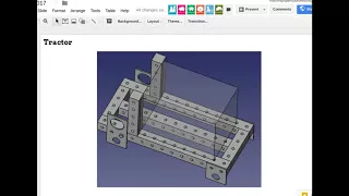
on
what
you
see
right
here,
that's
just
a
frame
with
the
power
cube
placeholder.
The
frame
here
needs
to
be
narrowed
down
to
20
inches,
it's
24
inches
right
now
we
see
the
motor
mount
plates.
A
The
the
idler
mounts,
I
believe
that
will,
let's
see,
will
log
I
think
he
I
believe
he's
done
the
updated
just
with
I
think
the
idler
sphere.
So,
let's
take
a
look
at
that,
but
the
idea
is
that
I've
allocated
different
roles
to
different
people
and
I
sent
some
emails
out
to
people
and
we're
keeping
the
master
master
tracking
of
that
on
the
life
track.
Construction
Set,
2017
page,
so
life
track
Construction,
Set
2017
page.
So
this
page
now
is
fully
seated
with
task
allocation.
A
A
People
are
the
left
column,
so
the
stories
are
people
here,
all
of
us
and
so
forth,
so
so
use
it.
Please
use
it.
We're
gonna
try
to
keep
tracks
track
of
tasks
so
that
we
don't
have
to
do
a
new
slide
every
work
meeting
it
is
more
convenient,
but
we
do
have
to
pay
attention
to
it.
So
please
either
manage
yourself
on
this.
When
you
have
completed
tasks
or
Joseph,
you
should
be
overlooking
that.
So
now
the
micro
track
concept
document
is
here
on
the
same
page,
the
master,
CAD
checklist.
A
A
So
there's
a
list
there
they're
just
a
list
here,
but
there's
another
part
library,
page
I'll,
show
you
but
there's
a
development
template
page
on
the
same
page,
so
we're
actually
trying
to
do
proper
record-keeping
of
all
the
different
assets
for
the
tractor
from
requirements.
Infographic
concept,
module
breakdown,
interface,
design,
3d,
CAD,
Bo,
M's,
build
instructions,
etc.
That's
all
to
be
filled
out
and
I
have
your
requested
that
Lex
generate
a
burndown
graph
for
us
so
that
we
can
see
this
as
a
burn
down,
which
is
the
percent
completed
over
time.
A
So
that
is
good
and
then
below
this.
You
have
all
the
previous
presentations
on
the
tractor
and
let's
go
to
the
original
part
library
page,
which
is
just
called
part
library
and
that's
where
actually
a
lot
of
the
parts
for
the
tractor
resides.
So
it's
got
everything
here,
but
here
you
can
see
a
visual
representation
of
all
these
different
things
like
the
motor,
the
either
mount
plates,
cetera,
sprocket
tracks,
a
lot
of
different
parts,
idlers
micro
truck
from
before
and
so
forth.
A
That's
the
policy
part
library
and,
as
far
as
looking
at
this,
take
a
look
at
that
alright,
so
we've
got
the
idlers
on
next.
We
need
the
so
this
is
by.
Will
he
just
added
the
idlers
and
a
way
it's
working,
so
these
could
actually
should
be
long,
shafts
cuz.
It
should
be
just
one
shaft,
so
you're
supporting
the
shaft.
With
these
two
plates
and
these
shafts
do
not
spin
the
bearings
make
the
idlers
spin
and
next
the
tracks
go
on
the
idlers
and
the
motors
go
inside
these.
A
A
A
So
that's
how
the
motor
looks
that's
an
approximation.
This
motor
is
not
exact,
but
it's.
Let
me
see
if
I'm
sharing
my
screen.
Yes,
I!
Am
it's
not
exact,
but
it's.
This
is
the
plate
where
the
sprocket
actually
mounts
right
on
this,
and
it's
got
five
bolts
on
this
plate
here.
This
is
a
good
representation
to
lengthen
with
are
pretty
much
approximately
good
and
a
mounting
plate
for
this
motor
would
go
right
here
on
this
surface.
That's
where
the
mounting
plate
goes
here.
A
A
Yeah
so
here
in
the
tractor,
the
Motors
fit
right
onto
that
plate.
The
four
bolts
go
on
this
plate.
Gonna
be
one
two
three
four
bolts
mounting
the
motor
the
motor
has
the
sprocket
up
on
the
sprocket
go
the
truck
tracks.
You
could
look
at
the
former
documents
for
how
the
tracks
look
and
we
can
use
the
identical
tracks.
If
we
close
up
the
distance
between
these
idlers,
then
you
can
have
a
tiny
track
and
that's
what
we're
gonna
do
for
the
rubber.
A
So
we
can
do
a
rubber
track
and
that's
that's
for
proof
of
concept
that
you
can
3d
print
tracks
and
that's
pretty
insane
stuff.
If
we
can
do
that,
six
pounds
of
print.
That
would
take
a
few
days.
But
if
you
have
a
huge
nozzle
like
we're
trying
to
move
to
the
larger
nozzles,
we're
only
at
0.5
nozzles,
but
we
want
to
do
the
one
point:
four
millimeter
nozzle
or
we're
just
spitting
that
rubber
out,
like
crazy
and
I
looked
at
pricing
of
rubber
I
think
we
can
get
me
from
China.
A
We
can
get
like
$8
per
kilogram
for
a
thermoplastic
urethane,
which
is
rubber.
It's
a
durable
rubber,
it's
used
in
tracks
and
that's
what
you
want
to
do
so
next
steps
here
are
to
mount
the
power
cube
into
its
proper
place.
Maybe
Roberto
you
can
do
that.
Do
the
loader
arms,
so
I've
assigned
it
to
Josh,
so
basically
create
a
geometry
of
loader
arms
based
on
the
kind
of
like
the
tornado.
So
the
the
mount
point
would
be
that
hole
right
there.
Perhaps
so
we
to
probably
do
some
kind
of
a
well
typically.
A
What
we
do
for
mounting
loader
arms
is
either
three
inch
or
two
inch
shaft,
so
basically
take
out
a
hole,
make
a
hole
in
this
larger
hole.
Put
in
a
large
shaft
and
the
shaft
once
again
goes
all
the
way
through.
Symmetry
is
a
good
design
concept,
so
you
want
to
send
it
and
send
the
shaft
all
the
way
through
just
like
on
the
bottom
here.
This
shaft
should
be
all
the
way
all
the
way
through.
A
This
is
not
gonna
hold
these
just
or
gonna
wobble,
so
the
shaft
needs
to
go
all
the
way
through
to
the
other
side.
There's
gonna
be
clamps,
so
clamps,
so
that
this
this
shaft
doesn't
move
back
and
forth
up
and
down
here
we're
gonna
have
clamps
underneath
there's
a
half-inch
space
underneath
there,
but
we
need
to
insert
clamps
which
look
like
if
we
go
through
the
part
library.
The
clamps
look
like
like
this
thing.
A
This
thing
is
not
drawn
completely,
but
this
would
have
the
two
bolts
one
on
each
side
and
you
can
look
at
I
believe
the
last
work
document
where
we
showed
real
picture
of
those
clamps.
That
was
I
believe
in
the
last
working
document,
which
was
it's
at
the
top
here.
The
last
work
document
from
the
design
sprint
is
up
here.
A
Motor
mounting
bolts
and
then
there's
the
one
is
the
motor
attaching
to
the
mount
plate
and
the
second
part
is
the
motor
mount
plate
attaching
to
the
frame.
So
there's
two
sets
of
bolts
there.
There's
quick
couplers
sprocket
details
details
the
clamps.
We
don't
have
a
tensioning
mechanism
on
this,
so
we
need
to
design
the
tensioning
mechanism
which
we're
not
there
yet
and
then
the
power
cube
Roberto
has
been
doing
a
lot
of
work
on
putting
that
together.
A
So
if
we
go
to
the
next
in
the
design,
doc,
here's
the
current
state
of
power
cube.
So
that's
what
we
have
20
inches
wide.
So
this
is
a
good
representation
of
the
current
one
and
I'm
gonna
open
up
the
real
real
one,
so
Roberto
log,
let's
download
it
from
Roberto
log.
So
we
can
take
a
look
at
that.
Maybe
you
can
do
that
as
well,
but
going
to
Roberto
log
I
will.
A
A
A
So
that's
what
you
want
to
do
in
the
next,
the
version
where
we
make
a
power
cube
that
can
be
used
and
multiplied
up
to
four
power
cubes,
because
we
want
to
build
a
64
horsepower
tractor.
In
that
case,
we're
gonna
enlarge
this
cooler,
so
they
have
coolers
that
are
bigger
than
this,
and
what
we
will
do
is
I
think
they
will
actually
fit
in
the
same
space.
So
we
can
replace
this
smaller
cooler,
which
is
enough
for
the
one
engine
plenty
for
one
engine.
A
A
A
A
We
can
verify
that,
but
I
can
tell
you
in
the
real
build
if
you
were
to
the
real
build,
has
a
30
in
3333
inch
frame
and
the
pump
is
like
similar
to
what
you
show
here
so
after
it's
30
that
pump
should
kind
of
move
back
towards
there.
So
this
implies
that
we
might
have
the
engine
or
the
pump
mount
here,
not
long
enough,
because
yeah
this
will
move
back
a
little
I
think
probably
the
coupler
here
is
probably
a
little
longer
or
the
engine
as
slightly
thin.
A
A
Okay
yeah,
so
the
engine
probably
needs
to
get
fatter
by
like
three
inches,
and
then
this
pump
would
move
back
like
to
literally
within
a
half
an
inch
to
an
inch
of
this
back
tank,
and
then
one
outstanding
task
is
also
to
draw
up
the
pump
coupler,
which
is
in
all
the
documents
there.
This
is
the
coupler.
A
It's
actually
a
it's,
not
one
of
these
couplers,
it's
the
Lovejoy
like
that
spider
coupler,
and
then
we
still
need
the
mount
of
the
mount
that
mounts
to
the
engine
plate
and
to
the
flange
of
the
hydraulic
pump,
so
that
mount
is
not
shown
here
which
needs
to
be
added,
still
pump
mount.
So
we
should
make
that
explicit
and
that
master
CAD
checklist.
Let's
see,
do
we
have
that
pump
mount.
A
A
D
A
A
That's
plenty,
but
we
didn't
put
the
loader
arms
into
this
main
main
thing
here.
So,
let's
put
this
item
number
24
here
would
be
the
loader
arms,
so
just
working
out
that
geometry
there
and
right
before
the
loader
arms.
One
easy
thing
to
do
about
the
loader
arms
is
one
first
in
insert
the
three
inch
shaft
and
I'm
not
three
inch.
Let's
do
the
now.
We
can
do
I
think
three
inches.
Okay,
now
three
inch
is
really
heavy.
A
Let's
do
two
inch
shaft
there
for
the
loader
arms,
but
if
we
want
to
make
those
loader
arms
scalable,
we
would
want
to
use
three
inch.
So,
let's
just
go:
let's
just
go
all
the
way
out.
Just
go:
go
with
the
super-heavy
three
and
shafts
for
the
loader
arms,
which
is
a
shaft,
that's
gonna
go
so
in
our
CAD.
A
Would
that
would
mean
is
that
a
shaft
just
goes
right
through
that,
just
the
same
as
these,
these
wheel,
shafts,
this
very
heavy
shaft
goes
right
through
that
space,
where
the
top
hole
is
and
upon
that
on
the
outside.
We
can
mount
the
loader
arms,
so
it's
a
very
heavy
attachment
for
the
loader
arms
and
then
outside
of
that.
What
we
want
to
do
is
clamp
it
down.
So
if
we
go
to,
let's
see
I
wanted
to
see
in
a
in
a
work
document
from
last
time.
We're
talking
about
this.
A
These
are
super
heavy-duty
clamps,
so
that
is
a
three-inch
clamp.
It
bolts
together
and
it
can
hold
things
like
the
loader
arms
on
or
it
can
hold
the
idler
shafts
so
that
there
is
no
axial
motion.
We
want
to
prevent
axial
motion,
meaning
the
shaft
doesn't
slip
out
of
the
the
hole,
doesn't
move
back
and
forth.
A
So
that's
what
we've
got
we
can
make
these
with
a
little
shorter,
like
maybe
you
can
get
them
down
as
short
as
just
a
one
bolt
clamp,
which
would
probably
be
useful
for
the
loader
arms,
where
you
don't
want
the
loader
arms
to
be
sticking
out
too
far
outside
of
the
body
of
the
tractor.
So
when
we
mount
the
loader
arms,
maybe
we
use
like
a
like
a
single
clamp,
which
means
that
it
just
takes
less
space
on
the
shaft,
so
the
shaft
can
be
shorter.
A
A
A
Tubing
is
what's
gonna
couple
like,
for
example,
if
we,
if
we
torch
the
hole
out
in
the
arms
you
want
to
put
in
that
tubing
as
a
guide
around
that,
so
that
it's
held
accurately
so
the
loader
shaft
is
held
accurately
in
place
and
in
here
what
we
can
do
it,
because
that
tubing
is
actually
now
four
inches.
That
would
cut
the
whole
tube
away.
So
what
we
can
do
is
not
shout
a
semicircle
on
top
and
just
weld
the
tubing
right
in
there,
and
that
would
be
a
solution
for
how
to
mount
the
shaft.
A
So
does
that
make
sense?
Well
this
tubing.
So
so
maybe
maybe
let's
break
that
down
into
the
two
tasks.
One
would
be
the
tubing
and
shaft
for
the
loader
arms
and
then
the
second
part
is
the
actual
geometry
of
the
loaders
themselves,
which
we
can't
use
this
tubing.
We
want
to
do
a
precise
geometry,
because
they're
here,
the
geometry
matters
or
otherwise
you'll
end
up
like
life
track.
Six.
The
geometry
of
the
the
loader
arms
is
kind
of
awkward
because
they're
the
precise,
like
the
inches
matter,
like
the
bulk,
just
crude
four
inch
tubes.
A
They
just
don't
work
well
because
you'd
have
to
cut
them
at
specific
angles,
so
you
might
as
well
cut
out
from
say,
half
inch
plate
cut
out
the
loader
arms
as
needed
for
the
more
precise
geometry.
If
you
look
at
what
the
Toro
dingo
does,
if
we
expand
that,
there's
is
what
looks
like
just
flat
plate
and
that
looks
like
problem
I,
don't
know
what
what
thickness
it
is
for
us.
Half
inch
would
be
relevant
half
inch
with
probably
some
reinforcements
we'll
have
to
see
exactly
how
it
looks,
but
half
inch
might
be
doable.
A
That's
that's
a
little
light.
It
would
have
to
be
reinforced.
It
would
have
to
be
bound
together
like
on
the
inside,
so
it
doesn't
wobble
back
and
forth,
but
at
best
you
probably
want
something
like
one-inch
plate
for
the
loader
arms.
That
would
be
pretty
good.
We
probably
might
want
to
go
just
right
to
one-inch,
because
that's
gonna
be
much
much
stiffer
than
half-inch
and
we
can
easily
cut
both
half
inch
and
one
inch
with
CNC
cutting.
We
aim
to
have
our
torch
table
up
and
running
so
just
to
go
into
this
this
thing.
A
So,
let's,
let's
just
specify
these
parts
just
more
explicitly
so
we've
got
the
three
bolt
clamp.
We've
got
row
above
row
below
the
loader
arm,
so
so
below
the
Lord
loader
arms.
We
have
the
loader
arm
bushing,
which
is
basically
the
three
inch
tubing.
That's
welded
welded
to
arms
and
we're
gonna,
clamp
it
and
we're
gonna
put
a
shaft
in
there.
So
so
that's
that's
how
it
looks
here
for
the
shaft
I'm
gonna
just
insert
that
picture
in
there
for
people's
reference.
A
A
A
A
D
A
D
D
D
A
Excellent
yeah,
that's
good,
and
next
so
after
the
loader
arm
geometry,
the
loader
arms
are
gonna
end
with
with
quick-connect
plate
for
attaching
implements,
and
for
that
we'll
we'll
have
to
think
about
that.
A
little
bit
the
media
thought
I
had
was
to
use
the
Bobcat
standard
mount
so
that
we
can
interchange
with
other
Bobcat
implements
now,
because
our
tractor
here
yeah
that's
a
very
popular
thing
that,
in
other
words,
any
implements
that
already
exist
for
the
Bobcat
standard,
which
are
you
know,
billions
of
equipment
out
there
billions
of
dollars
worth
of
equipment
out
there.
A
The
question
is:
will
they
fit
on
our
tractor?
Because
this
thing
is
gonna
weigh
about
2,000
pounds
when
done,
and
the
width
is
41
inches
and
we're
going
by
the
industry
standard
from
the
Toro
dingo,
it's
41
inches.
So
currently
we
have
this.
Our
width,
so
is
the
Bobcat
quick
attach.
Does
that
fit
within
41
inches?
Right
now
to
the
outside
of
the
beast
these
shafts
here
we
should
have
41
inches
where
we
at
right
now,
forty
to
sixty
four,
not
bad.
A
We
want
to
just
poke
that
shaft
in
maybe
a
little
bit
or
maybe
that's
what
we
get.
We
get
40
to
26
inches.
Maybe
we
have
to
live
with
that,
but
we
just
wanted
to
get
it
as
tight
as
possible
so
that
we
can
get
into
tight
spaces,
and
maybe
we
can,
like
you
know,
shrink
up
that.
You
know
whatever
that
half
inch
there,
so
the
the
idlers
are
right
next
to
the
body,
but
this
is
good.
I
mean
that's,
that's
a
very
compact
machine
right
there
good
and
let's
see,
is
Achmed
here.
A
A
The
way
to
do
the
tracks
would
be
to
take
the
existing
and
I
have
to
be
super.
Precise
I
mean
just
just
for
because
we
know
they
fit
and
and
so
forth,
but
to
do
the
track.
Take
the
track
piece
which
is
in
the
part
library.
It's
the
tracks
unit
do
a
path,
array
and
freecad,
which
is
you
draw
a
line,
and
then
you
put
a
item
an
object
along
that
path
array.
Then
you
can
get
the
whole
track
and
you
can
make
it
tangent.
A
So
if
you
make
the
track
piece
tangent
to
that
shape,
you
can
just
do
polyline.
The
simplest
implementation
of
the
tracks
would
be
polyline.
You
draw
yourself
a
line
that
matches
the
protein,
the
kind
of
like
what
we
need
so
draw
the
in
this.
In
this
picture,
you
would
draw
yourself
the
a
line
that
looks
like
the
triangular
tracks
and
then
do
the
path
array
using
the
individual
track
piece
as
the
object
that
you
attach
to
the
path
array
and
that
will
get
your
tracks.
A
That
should
be
pretty
straightforward
now,
with
free
CAD
using
the
capacity
of
free,
CAD,
okay,
looking
at
the
back
to
the
spreadsheet,
so
we
had
Achmed
on
that
now.
Somebody
else
wants
to
jump
in
there,
too
I
mean.
Basically
we
got
to
complete
all
these
blank
spots
here
as
soon
as
we
can
and
so
forth.
A
So
I'd
like
to
post
the
event
announcement
for
this
within
two
weeks,
so
we
should
have
a
good
conceptual
design
of
the
the
tractor
here
now,
the
next
step
after
we
perfect
this
16
horsepower
version
the
tiny
one
what
we
want
to
do
is
so.
This
is
our
working
document
here,
that's
the
frame
but
for
a
64
horse
version,
meaning
we
talked
about
the
scaling
of
that
and
we
talked
about
this
configuration
here.
Just
this.
The
large
tractor
would
be
a
wider
frame
and
two
sections
like
this.
A
So
that's
that
all
right,
let's
move
on
in
the
meeting
here-
and
that
is
just
to
cover
some
more
ground
here.
So
we
got
the
power
cube.
We
got
the
frame
in
progress,
we're
gonna
try
to
go
with.
We
did
a
gasifier
last
time,
so
we're
gonna
go
nuts
and
for
the
october
27
29
build
we're.
Gonna,
add
a
gasifier
to
this.
A
Now,
let's
this,
this
is
gonna
rely
on
the
CNC
torch
table.
So
this
is
the
latest.
This
is
from
a
manual.
This
is
this:
is
the
latest
iteration
of
the
carriages
for
the
the
CNC
torch
table?
We
had
this
whole
thing.
3D
printed,
we
went
to
smaller
3d
prints,
so
they're
faster
to
print
and
metal
plates
on
top
and
bottom,
so
that
this
is
super
stiff.
So
this
is
our
current
implementation
of
the
the
carriage.
A
What
we're
going
with
right
now
is
using
3/4
inch,
steel
pipe
schedule.
40.
We
found
that
for
the
12-foot
long
axis
of
the
torch
table,
the
torch
table
is
large.
It's
it's
5
by
10
or
or
6
by
12
feet
and
the
solid
axes
weigh
a
lot.
So
we
wanted
to
go
to
a
little
lighter
version.
So
it's
better.
So
we
want
to
use
3/4
inch
pipe
now.
3/4
inch
pipe
is
not
regular.
It's
not
one-inch.
It's
1.05
inch,
so
we're
gonna
modify
the
bushings
there
to
do
that,
but
that's
in
progress.
A
A
He
didn't
particularly
like
this
system
because
he
wants
to
go
to
actually
two
like
bearings
riding
on
Rails,
which
is
a
completely
different
design,
but
since
we
want
to
use
the
universal
axis
as
the
general
design
pattern,
because
we're
gonna
scale
that
up
to
2
inch
shafts,
we
want
to
continue
the
same
design
process
as
opposed
to
top
making
it
completely
different
and
therefore,
by
keeping
it
the
same,
you
reduce
the
part,
count
and
complexity
of
the
entire
global
village.
Construction
set
significantly.
So
that's
a
big
point
and
initial
calculations
per
say.
A
If
you
have
two
inch
shafts
instead
of
one
inch
shafts
here
so
much
larger
piece,
the
calculations
they
are,
you
get
a
you,
get
about
half
a
thousand
deflection
on
a
4x4
CNC
machine
if
you
used
to
in
shaft.
So
the
strength
is
there
like
some
of
the
argument
against
these
long
shafts?
Is
that
you
don't
have
enough
strength,
but
you
can
design
the
strength
in
there.
You
can
use
thicker
rods.
A
You
can
use
a
smaller
machine
like
four
four
by
four
feet.
No
I
think
I
actually
did
that
for
two
by
two
feet.
Working
area
see
heavy-duty
CNC
machine
deflection
on
two
and
shafts.
If
you
do
calculations
basic
deflection
of
steel
for
a
steel
tube,
you
get
like
I,
think
I
got
like
1/2
or
1/3
of
a
thousandth,
of
an
inch
of
deflection,
which
is
quite
sufficient
for
heavy-duty
CNC.
Precision
machining,
so
we're
going
with
this
continuing
on
this
moving
forward.
But
we
gotta
get
to
this
oh
yeah,
but
I
mentioned
already
that
we're
gonna.
A
Do
the
build
workshop
for
the
CNC
torch
here
on
October
14,
which
is
two
weeks
before
the
the
tractor
workshop,
so
I
I'm
aiming
to
actually
get
that
design
up
there
for
event
announcement
by
this
weekend.
Let's
see
if
I
can
do
that.
Okay-
maybe
maybe
I'm
gonna-
try
to
see
if
Michelle
can
help
on
that
emmanuel
is
actually
currently
designing
a
different
version,
so
he's
kind
of
like
working
this
design,
if
you
may
say
to
basically
the
rail
version
with
with
metal
rollin
metal
bearings
riding
on
Rails.
A
So
that's
not
that's
a
fork
of
our
design,
not
consistent
with
it
we'll
see.
If
we
can
get
this
going,
I'm
gonna
see
if
I
can
enlist
Michelle,
who
actually
initially
designed
these
one-inch
carriages
to
continue
work
on
that
okay.
This
is
Michelle's
work
on
WebGL,
so
we're
getting
a
whole
tutorial
on
how
to
generate
WebGL
using
free
cat
and
and
blender.
So
this
is
what
he's
capable
of
doing.
This
is
beautiful,
he's
doing
exploded
apart
animations.
A
The
first
tutorial
is
gonna,
be
how
do
you
generate
just
to
the
3d
for
that
you
can
embed
and
he's
working
with
I.
Think
Jose
is
gonna
pipe
in
on
that
regarding
the
workflow,
with
with
get
of
how
you
can
store
the
actual
images,
because
in
this
WebGL
documentation
that
you
can
embed
so
WebGL,
you
can
embed
in
your
website,
but
it
has
to
the
data.
Data
has
to
reside
somewhere.
So
actually
we
were
thinking
about
github
as
the
place
where
the
data
resides
so
we're
developing
that
workflow
step.
A
One
is
just
to
get
excellent
3d
manipulable
images
you
can
rotate
them
pan
and
zoom,
and
the
next
one
is
actually
where
you
can
do
explode
apart,
animations,
where
you
click
on
things,
and
you
can
explode
things.
So
we're
getting
that
documentation
up
and
running
so
hopefully
everyone
on
the
team
is
gonna.
Get
that
going
okay.
This
is
saudi-arabia
workshop
preparation
on
the
3d
printer
workshop.
Well,
we
don't
have
a
scheduled
date
for
it
yet,
but
they're
working,
they're,
printing
out
parts
here,
you
can
see
some
warped
parts.
A
Here's
some
better
parts
in
PA
that
the
ABS
is
hard
to
print
with
it
warps
a
lot.
So
a
PLA
is
much
better
as
you
see
here,
but
that's
being
prototyped,
that's
about
all
the
progress
we've
got
for
this
week.
So
keep
going!
Please
do
the
look
at
the
ociso
as
task
one
and
second,
please
do
the
different
allotted
tasks
here.
If
you're
not
doing
anything,
please
put
your
name
somewhere
I'm
trying
to
put
in
honde
go
there's
your
Armand
I
hope
hope.
A
That's
it
explained
here,
but
if
you've
got
any
questions,
email
me,
what
I'm
expecting
is
that
everybody
would,
if
you
know
we're
expecting
to
fill
out
this
the
spreadsheet,
and
if
you
have
any
questions,
please
ask:
we've
got
the
email
thread
going
on
email
so
continue.
So
does
anyone
have
any
questions
right
now?
As
far
as
the
overall
design
of
the
detractor
and
empower
cube
and
everything
else,
what
else
can
I
explain
any
questions
here.
C
A
Yeah,
so
let's
take
a
look
at
some
of
the
questions
so
from
the
back.
Let's
go
at
Jose.
Scrummy
is
not
the
only
thing
that
we
have
dropped.
We
should
have
some
control
change
to
avoid
dropping
good
practices
and
procedures,
especially
because
new
people
are
coming
in
some
process.
Control
flow
is
good,
well
agreed,
but
the
effort
to
do
that,
it
just
hasn't
happened.
So
how
do
we
address
that?
Any
solutions.
A
C
C
A
Well,
that's
a
good
idea.
We
just
need
the
bodies
to
do
it
and
people
to
continue
with
the
meetings
and
so
forth.
So
that's
that's
good.
That's
that
definitely
would
help
cuz
yeah
I
mean
to
watch
the
videos
a
little
long,
but
if
it's
an
hour,
what
I
do
typically
is
I
put
it
up
on
YouTube
on
double
speed.
So
it
only
takes
you
a
half
hour
and
you
can
even
undone
speed.
You
can
still
go
through
like
skipping
through
it
to
relevant
parts.
A
C
A
A
I'm
kind
of
you
know
pretty
much
spearheading
the
meetings,
but
we
need
some
help
on
that,
like
you
know
like
Joseph,
if
you
could
do
some
some
stuff
like
what
like
I
mean
preparing
kind
of
like
it
being
really
on
top
of
what
everyone
is
doing,
you
know
and
clarity
on
the
role
allocation
that
that
would
help,
and
it's
I
know
that
we're
skipping
around
a
bit.
So
things
are
dynamic.
It's
a
dynamic,
agile
process,
any
other
thoughts
on
the
topic.
A
E
A
E
F
C
A
C
A
And
so
what
about
one
specific
question?
You
know
how
we
have
the
version
history
and
we
can
download
any
back
version.
How
do
you
do
that
in
github?
Is
that
as
easy
as
the
wiki,
for
example,
because
we're
putting
all
the
files
on
the
wiki
right
now
and
it's
nice,
because
you
have
comments
and
you
can
download
the
old
versions
redly?
Is
that
as
easy.
A
Yeah,
if
a
clear
workflow
merges
that
that
people
use
on
github,
then
we
can
try
I
mean
one.
One.
Other
thing
is
the
learning
curve
of
github
as
well.
That
has
to
be
considered
because
we
do
know
that
that
Google,
Docs
and
and
wiki's
work
we
that's
proven.
So
that's
what
I've
been
doing
so
far.
I
think
we'll
have
to
continue
and
see
how.
C
A
C
A
D
D
D
D
G
A
Yeah,
okay,
yeah
I
mean
maybe
we
just
gotta
go.
Try
it
on
us
on
a
certain
certain
test
case
to
see
how
it
works
and
then
take
the
hit
of
just
a
little
bit
of
learning
curve
on
that,
and
of
course
it
will
have
a
little
learning
curve,
but
it
will
make
some
things
more
efficient,
I'm
wondering
if
it's
worthwhile
to
we
always
like
multiple
solutions,
and
there
may
be
people
who
really
gravitate
to
that-
can
definitely
use
it.
But
what
about
the
people
that
are
the
total
beginners?
Are
they
going
to
be
left
behind?
C
A
G
G
Turn
off
issues
and
weekend
all
the
other
ones,
because
if
you
have,
if
you
support
issues
and
all
of
the
project
or
we
use
it
all
the
projects,
then
it's
going
to
get
disorganized
and
you
won't
be
able
to
aggregate
things.
So
if
we
go
down
using
github
for
tracking
LLC
work,
it
is
better
to
have
one.
You
choose
one
repo
to
do
that
and
then
all
issues
should
go
there
and
all
the
management
using
that
one
repo.
You
can
still
have
lots
of
other
repos
broker
source
code,
but
it
should
be
standard.
G
A
Okay
and
we
can
I
think
we
can
make
both
reconcile
both
of
them
as
when
we
finally
have
yeah
yeah
I
mean
I,
don't
think
both
are
exclusive.
I
think
we
can
do
both
and,
of
course,
we're
not
gonna
just
trash
the
wiki,
so
I
think
yeah.
We
should
get
ready
for
yeah.
We
should
just
experiment
a
little
more
with
how
exactly
to
integrate
that
seamlessly
into
our
workflow
yeah.
D
D
A
Yeah
yeah
so
definitely
yeah.
Definitely
we
gotta,
maybe
upgrade
our
skill
set
here
and
promote
that,
but
look
at
that
screen
of
mine
there.
This
is
Michelle's
work.
The
exploded,
ramps
board
man.
This
is
michelle.
Amazing
work
man,
so
I
look
forward
to
all
of
us
learning
how
to
do
this.
This
is
most
amazing
thanks
a
lot.
No
we'll
continue
on
that.
I
got
actually
get
going
because
we're
talking
I'm
talking
to
Salaam
about
the
computer
vision
on
a
tractor,
so
I
need
to
do
that.
A
So
we
need
to
get
off
the
call
here,
but
please
continue
on
the
work.
Let's
see
the
last
question
that
will
will
entertain
here.
So
so,
how
will
the
logs
be
handled
new
logs
and
time?
We
have
a
and
they
are
in
separate
database
and
currently
not
editable.
What
about
searchable?
Also
direct
wiki
links?
Don't
work
can
be
added.
G
Yeah
then,
as
far
as
the
search
I
mean,
I
can
definitely
not
search
but
to
be
able
to
start
to
do
ones,
search
info
box
that
searches
both
the
wiki
and
the
log
that'll
be
a
little
bit
trickier
to
do,
and
then,
as
far
as
being
able
to
edit
them.
That's
once
you
can
log
in
physics
that
that
currently
exists.
You
can't
edit
that,
but
you
have
to
be
low
log
in
to
edit
them.
A
Yeah
and
oh
yeah,
who
did
the
open
PLM
called
I
open,
PLM
command,
who
said
that
Stephen?
Well,
if
you
can
tell
us,
I
was
just
looking
at
that
yesterday
and
if
it's
in
a
good
state
of
development,
we
should
absolutely
do
it
because
then
they
from
what
I've
heard
just
on
the
web
that
looks
like
they
have
like
automatic
bill
of
material
generation.
I
come
up
some
of
the
critical
workflows
that
we
need
to
go
from
CAD
to
actual
production.
So
we
need
to
look
at
that.
I,
don't
know
enough
about
it.
A
So
if
anyone
knows
more
about
open,
PR,
I'm
Stephen,
let's
let's
talk
about
it
but
yeah.
We
got
to
look
into
that
and
the
thing
there
is.
We
need
to
find
somebody
who
knows
about
that.
Well,
I
just
don't
know
the
answer
right
now.
We
need
to
find
somebody
from
the
open
PLM
to
see
if,
basically,
what
the
status
is.
A
The
best
thing
is
to
just
check
in
with
some
of
their
leadership
or
our
forums
or
whatever,
to
see
what
what
exactly
is
possible
right
now
and
also
depends
on
the
state
of
development
of
that
project.
If
it's
a
well
developed
project,
if
it's
got
a
good
development
going
on,
yes,
it's
worth
it,
but
if
it's
gonna
be
a
stalled
project,
it's
not
worth
investing
in
that.
So
we
need
to
find
out
some
of
those
things.
A
Okay,
guys
I
need
to
get
going
right
now
for
the
next
meeting,
but
thanks
a
lot
we'll
continue
so
continue
on
a
CAD
continue
on
other
stuff
and
we'll
keep
going
and
next
time
we're
gonna
have
a
note-taker,
and
please
update
your
logs
in
the
new
interface
as
well
as
download.
The
OSC
ISO
put
your
comments.
If
it
works,
for
you
doesn't
take
a
long
time
just
downloaded
and
make
the
USB
takes
an
hour
thanks
a
lot.
Everyone.