►
From YouTube: Stepper Motor Controllers - OSE Design Guide
Description
https://wiki.opensourceecology.org/wiki/OSE_Design_Manual_-_Stepper_Motor_Controllers
-----------------
What you see here at Open Source Ecology is an ambitious open source project for the common good. Join our development team:
http://opensourceecology.org/wiki/OSE_Developers
We run One Day Extreme Build workshops in many locations. Please put yourself on our map if you'd like us to host a workshop near you:
https://microfactory.opensourceecology.org/request-a-workshop/
Take a minute to subscribe to our email newsletter (updates, workshops, etc): http://bit.ly/1LtcM44
A
A
Stepper
motors
are
what
we
use
to
generate
precision
motion
here
in
our
system
like
the
3d,
printer
and
larger
machines.
So
that's
ready,
off-the-shelf
solution
that
we
can
incorporate
in
the
modular
design
language.
So
what
we
want
to
know
what
we
need
to
know
about
designing
with
four
stepper
motors
and
driving
them
is
where
to
source
them
and
then
how
to
drive
them.
A
So
the
ramps
board
on
the
universal
controller
already
has
small
stepper
drivers
for
a
small
stepper
motors
and
what
our
stepper
motors,
let's
start
with
some
some
definitions
of
there's
a
good
diagram
on
Wikipedia.
Actually
so
stepper
motors
are
devices
which,
let's
put
a
stepper
motor
image
image
of
a
standard
stepper
motor.
These
are
stepper
motors
images.
You
can
get
these
everywhere.
A
We
use
NEMA
17
size,
stepper
motors,
the
NEMA
rating,
like
17
23
30
34
refers
to
the
inch
size
between
the
size
of
the
mounting
plate,
NEMA
17,
being
the
smallest
I,
think
it's
1.7
inches
I
believe
is
it
across
the
face
or
it
might
be
next
to
the
two
holes
adjacent
to
each
other.
But
stepper
motors
look
like
this:
they
have
internally.
A
Sorry,
okay,
so
here's
a
diagram
on
Wikipedia,
here's,
a
diagram
of
what
the
stepper
motor
looks
like
inside.
It's
got
a
number
of
teeth
on
on
an
internal
rotor,
and
it's
got
a
number
of
windings
on
the
inside.
Just
can
take
a
look
at
the
image
like
this
here
for
a
basic
diagram.
Rotors
the
rotors
have
many
teeth
on
them.
Typically,
they
have
about
50
teeth,
there's
a
shaft
there's
a
body
and
there's
magnetic
windings
as
the
stator
there's
a
bunch
of
magnetic
windings.
A
A
For
the
ramps
stepper
driver,
you
also
have
five
five
phase
motors,
but
how
okay?
So
how
does
this
work?
How
do
you
get
precise
motion
along
an
angle
like
200
steps
per
revolution
out
of
a
stepper
motor?
Please
look
at
the
Wikipedia
diagram.
That
really
explains
it
quite
well,
and
essentially
you
have
this
interior
rotor
in
the
heat.
In
this
example,
here
we've
got
25
teeth
and
you're,
activating
four
coils.
A
Okay,
when
you
activate
what
you
see
is
that
when
you
activate
each
coil
the
teeth
line
up
against
one
another,
so
that
means
these
coils
have
to
be
offset
a
little
bit
by
a
fraction
of
a
tooth
from
each
other,
so
that
when
you
energize
one
you,
you
have
a
slight
motion
to
in
given
direction.
So
in
this
example
here
the
way
the
math
works
out,
there's
20
and
this
example,
it's
25
steps
and
4
teeth
for
4
magnetic
coils
there.
In
the
real
case,
you
have
50
teeth
and
two
sets
of
different
coils.
A
A
A
You
have
a
concept
of
micro,
stepping
where
you're
not
only
turning
on
one
set
of
coils
at
a
time,
but
partially
turning
on
one
so
giving
a
little
bit
of
juice
to
one
and
then
some
to
another.
So
you
have
the
idea
of
micro
stepping
within
stepper
motors
altogether,
you
get
in
a
typical
scenario
like
we
use.
We
get
200
steps
per
revolution
with
micro
stepping,
and
we
can
divide
round
motion
into
precise
motion.
A
B
A
Very
very,
very
high
precision
from
these
stepper
motors,
but
now
with
the
the
full
stepping
you
get
the
most
strength
with
the
further
and
further
micro
stepping
and
get
less
less
torque,
but
you're
able
to
pull
hold
right.
So
the
idea
there
is
within
stepper
motors,
you
have
a
holding
torque
when,
when
stepper
motors
are
stationary
they're
not
moving,
they
can
hold
the
most,
they
can
hold
the
most
torque
once
they
start
moving
you're
partially
energizing
one
call
than
another.
A
So
actually
the
torque
goes
down
and
a
torque
curve
goes
such
that
you're
very
high
torque
to
about
500
rpm
typically.
So
this
is
a
typical
kind
of
a
rpm
curve
for
a
stepper
motor
torque
on
the
left
axis
versus
speed.
So
you
you're
full
you're
about
full
power
from
zero
to
500.
Then
you
see
a
gradual
drop,
but
you
can.
You
can
go
quite
quite
a
bit
down
to
20%
of
the
torques
up
to
say,
like
2000
rpm,
so
it's
still
pretty
fast,
but
you
get
two
very
useful.
A
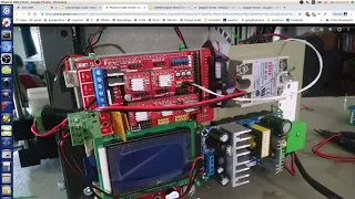
Unwraps
we
implement
microstepping.
So
the
very
practical
thing
is
you
see
these?
This
is
a
ramps
board
and
on
ramps
you
implement
the
micro
stepping
by
putting
in
Japanese,
so
it's
either
one
two
or
three
jumpers
that
correspond
to
half
quarter,
sixteenth,
eighth
and
sixteen
micro
stepping,
depending
on
which
jumpers
you
put
in
in
our
case
here.
We
use
all
the
three
jumpers
and
gets
us
16
micro,
stepping
which
is
the
limit
of
the
ramps
board.
A
So
the
stepper
driver
what
it's
doing
it's
creating
a
set
of
pulses
at
varying
time
intervals
when
you
have
Mike
micro
stepping
so
there's
a
little
little
microprocessor
on
board
each
of
these
stepper
drivers,
which
allows
you
to
do
just
that.
So
it's
not
you
don't
just
plug
in
a
stepper
motor
into
the
wall.
You
give
it
a
finding
control,
pull
sequence
and
that
pulse
sequence
is
controlled
by
Marlin.
A
Marlin
gives
the
stepper
drivers
basically
step
direction
and
enable
signals,
and
how
do
you?
How
do
you
control
the
speed,
be
controlled
by
how
fast
you're
switching
the
poles
so
the
function?
The
speed
function
of
that
at
that
level
the
stepper
drivers
interpret.
They
give
you
the
pulse
sequence,
but
the
actual
speed
all
you're
giving
to
the
stepper
driver
itself
is
just
stepping
enable
direction
at
no
I'm,
actually
not
sure
about
that.
Who
is
doing
the
timing
for
the
particular
speed.
Is
it
the
Arduino?
B
B
A
B
A
We
can
the
the
power
of
the
universal
controllers
that
you
can
plug
in
either
your
small
little
Pololu
style,
stepper
drivers
here
right
into
the
board
or
you
can
use
bigger
ones.
We
mentioned
that
you
only
need
three
three
properties.
You
need
to
enable
step
and
Direction
signals
so
underneath
from
the
arduino
you're
only
using
three
pins
underneath
these
stepper
drivers,
so
each
step
or
driver.
A
Stepper
driver
just
to
show
a
picture
of
these
jars.
Each
of
these
is
a
small
little
little
chip
like
this
cost
of
dollars.
So
so
that's
our
individual
stepper
driver
with
the
heat
sinks.
On
top
what
you
see
for
the
metallic
object?
There's
heat
sinks
because
that's
the
microprocessor
there
gets
a
little
hot,
but
these
are
quite
accessible.
You
can,
if
it
breaks,
if
it
burns
out,
you
can
you
can
replace
it.
It's
a
modular
system,
but
the
power
of
this
comes
when
you
plug
in
an
external
stepper
driver.
A
So
let's
talk
about
how
that
is
done.
So,
let's
start
with
options
that
you
already
have
that
fit
in
that
form
factor.
So
right
now
off
the
shelf.
You
can
also
get
these
other
Pololu
like
stepper
drivers,
either
these
are
the
TMC
to
208
same
form,
factor
but
their
advantages.
They
actually
provide
silent
operation.
So
you
do
not
hear
the
the
stepper
motors
humming
and
making
music
it's
pretty
silent.
There's
another
option
advanced
more,
even
more
advanced
stepper
drivers.
A
These
are
the
these
are
called
try
now
these
are
clones,
but
try
Namek
stepper
drivers
where
also
the
same
form
factor
gets
you
additional
properties.
You
can
actually
measure
the
current
that
that
the
stepper
motor
is
taking,
and
it
can
allow
you
to
remember
where
you
were
so.
If
the
power
goes
off,
you
can
continue
where
you
left
off.
So
the
usefulness
here
one
is
that
you
can
have
silent
operation
two.
You
can
have
the
ability
to
use
the
stepper
motor
itself
as
the
end
stop
sensor.
A
Basically,
when
you
hit
into
the
limit
of
where
the
axis
where
a
given
axis
can
go,
you
detect
a
higher
current
and
you're
actually
measuring
that,
instead
of
using
end
stuff.
So
this
is
this
allows
you
to
use
one
less
component
in
the
3d
printer
or
universal
access
system.
So
that's
very
useful
would
be
something
good
to
develop
on
our
our
side.
A
If
you
want
to
replace
just
remove
need
of
using
and
stops
which
take
you
a
little
bit
to
fabricate
and
put
on
it's
less
parts,
less
parts,
the
better
to
put
more
logic
into
the
electronic
components,
instead
of
additional
components
that
new
ones
that
as
opposed
to
ones,
that
already
exist
that
you're
using
so
you're
using
the
stepper
drivers
already
they
have
it's
like
having
a
built-in
end,
stop
which
is
awesome
and
that's
a
common
feature.
These
days
that
came
out
maybe
a
couple
of
years
ago.
A
Right
now,
a
lot
of
people
are
using
that
we
haven't
implemented
that
yet,
but
now
the
power
comes
from
using
larger
stepper
drivers.
So
take
this
much
larger
current
handling,
the
small
steppers
they
get
you
up
to
about
an
amp
of
current.
You
can
buy
external
external
stepper
drivers
that
get
you
up
to
four.
These
are
four,
so
they
cost
four
amps
of
current
up
to
50
volts,
so
you're
talking
about
eleven
dollars
for
one
of
these
off
Amazon
and
you
can
have
these
that
are
larger
and
larger.
A
These
are
just
particular
ones
that
are
good
enough
for
the
larger
NEMA
23
motors.
That
we're
using
the
high
torque
for
25
inch
ounce
motors
that
we're
using
like
we're
using
on
a
two
inch
universal
access
system
for
the
heavy-duty
mill.
These
are
sufficient
for
that
kind
of
level
of
operation.
You
can
get
larger
ones
as
well,
but
how
exactly
do
you
connect
them?
A
You
want
to
take
a
look
at
start,
looking
at
getting
familiar,
what
the
ramps
wiring
down
diagram
really
looks
like
so
here's
a
simple
way,
so
the
stepper
drivers
are
taken
off
here
and
use
three
pins
off
the
actual
stepper
driver
connections,
which
are
enable
direction
and
pulse
or
step.
So
you
essentially
connecting
three
wires
plus
a
five
volt
to
the
stepper
stepper
driver
and
then
on
the
other
side
of
that
the
other
green
terminals
here
you're
connecting
your
stepper
motors
through
four
wires.
So
these
are
simple
bipolar.
A
The
two
phase,
stepper
motors
phase,
a
and
phase
B.
Then
you
also
have
bolt
voltage
and
ground,
so
that's
the
you
would
have
a
power
supply
connecting
to
the
other
part
other
side
of
this
external
stepper
driver,
which
in
this
case
these
are
actually
up
to
DC
nine
242
volts.
So
you
can
run
your
steppers
stepper
motors
up
to
42
volts.
That
means
you
get
higher
speeds.
Yeah.
The
higher
speeds
at
higher
voltage
refer
to
one
of
the
properties
of
of
the
stepper
motor,
which
is
its
inductance
there's
both
resistance
and
inductance.
A
In
a
stepper
motor,
the
higher
the
voltage
you
can
push
through
the
lower
the
inductive
effects.
In
other
words,
you
can
get
it
up
to
speed
faster
and
therefore
you're
able
to
achieve
higher
speeds,
because
at
a
certain
point
you
get
back
EMF
from
the
coils
and
that
back
EMF
reduces
effectively
the
voltage
you're
applying
to
it.
So
if
you
have
higher
voltage
to
push
you're
effectively,
driving
can
drive
a
stepper
more
flat
motor
faster.
So
where
we
looked
at
a
a
speed
diagram
of
a.
A
Initially,
we
use
12
volts
on
our
ramps
right
now,
we're
at
24
volts.
But
if
you've
got
this
up
to
say
40
volts,
maybe
the
curve
would
be
perhaps
a
little
higher,
so
you
can
gain
something.
I,
don't
know
exactly
how.
But
if
you
you
can
Google
dependence
of
stepper
motor
speed,
torque
on
voltage,
and
you
probably
get
some
curves
here
that
show
that
at
lower
voltages
you
can
only
go
so
fast
with
a
given
stepper
driver.
So
you
look
at
images
and
actually
yeah
I
wasn't
I
wasn't
really
able
to
find.
A
A
You
get
faster
speeds,
I'm,
not
sure,
that's
exactly
what
that
is,
though
I'm
not
sure,
but
the
higher
the
voltage
you're
able
to
achieve
higher
speeds
and
that
will
matter
when
you're
pushing
the
performance
if
you're
pushing
the
performance
of
your
your
machine
that
you're
designing
so
ramps
in
general.
Now,
what's
the
ramp
schematic
image,
we
should
get
familiar
with
us
since
we
use
this
all
the
time.
So
that's
your
ramps.
A
The
two
row
sockets,
which
you
see
five
of
them,
the
actual
plugs
for
the
steppers,
where
you
plug
plug
the
stepper
motor
wire
to
the
stepper
motor.
Are
these
ones
in
green,
a
set
of
four?
So
in
our
case
we're
using
an
extruder
we're
using
the
X
we're
using
the
Y
we're
at
we're
actually
at
taking
the
extruder
one
and
using
as
the
second
Y
since
we
have
a
two
Y
axis
system.
So
that's
we've
done
that
in
Marlin.
B
B
B
A
A
A
So
there's
the
locations
of
the
jumpers.
I
mentioned
that
you
said
the
microstepping.
We
always
use
three
where
you
we
use
sixteen
microstepping,
some
other
things
that
LCD
display
plugs
into
these
long
long
rows
here,
there's
power
so
in
our
current
system,
we're
plugging
in
twelve
volts
into
the
up
upper
connector
and
we're
changing
this
twelve
volts
at
the
bottom
to
twenty
four
by
removing
that
diode
right
there.
So
so
we're
hacking
our
system
to
the
ramps
on
24,
volts
DC,
and
you
can
see
that
on
a
wiki
ramps.
A
Ramps
on
24
volts
is
the
wiki
page
where
we
show
exactly
what
are
the
modifications
to
the
system
in
order
to
run
that,
so
it's
a
simple
diagram
of
how
we're
wiring
up
the
ramps
in
our
case,
where
we're
plugging
in
both
12
and
24
into
the
ramps,
because
for
12,
where
do
we
use
the
12
I,
don't
even
know
where
we
use
the
12?
Where
are
we
using
before?
If
I
know,
we
use
everything
pretty
much
on
24,
because
the
fans,
the
heater
everything.
A
B
A
An
end
stop
that's
what
we're
doing
so,
we're
just
using
right
now
we're
using
that
terminal,
essentially
as
a
power
source
for
the
step-down,
we're
using
a
12
volt
to
5
volt
little
little
board
that
we
feed
into
the
end
stop
pins.
So
I
guess:
there's
nothing
on
board
that
uses
that
12!
No!
No,
there
is
I'm.
Sorry,
there
is
the
one
thing
that
does
use
it.
The
12
volts
is
the
signal
to
the
relay,
so
the
hotbed
is
activated
by
12
volts,
which
activates
the
solid
state
relay
to
120
AC
heat
bed.
A
A
I
mentioned
that
we
cannot
power
the
Arduino
ramp
system
from
12
volts
because
it
blows
it
blows
that
voltage
regulator
because
we
have
the
LCD
and
so
many
components
on
top
so
we're
using
a
reduction
of
12
volts
to
5
volts
fed
through
the
last
and
stop
pins,
which
are
empty
through
the
red
and
black
that
you
see
here,
we're
actually
feeding
power
to
that
where
the
red
is
Plus
and
the
black
is
negative.
So
that's
a
brief
overview
here.
A
Well,
there's
yeah
so
ignore
this
barrel
jack
here
that
turns
out
not
to
work
okay,
so
going
back
to
the
design
document,
so
that's
raps
in
general,
but
more
specifically,
if
you
ever
need
to
pack
it,
you
want
to
look
at
the
deeper
diagram.
That's
that's
like
right
here,
which
shows
you
more
information
about.
What's
underneath
here.
So,
for
example,
under
each
of
these
double
row,
stepper
motors
you'll
see,
if
you
look
at
the
fine
print
there's
the
e
n
under
the
pin
here
the
first
pin
and
then
when
you
go
farther,
there's
step.
A
You
can
read
this
step
there
SD
and
then
dir
for
direction
so
use
this.
Pin
here
at
the
beginning
and
these
two
pins,
when
you're
connecting
to
the
stepper
external
stepper
drivers,
so
that
helps
you
if
you
these
diagrams,
are
all
over
the
internet.
So
when
you
pull
it
up,
if
you
forget
how
to
connect
your
two
external
Toshiba,
6600
stepper
driver,
you
can
look
at
this
for
enable
step
in
directions,
and
we
also
have
done
this
for
the
CNC
torch
table.
A
A
So
if
you
want
to
design
your
own
controller,
there
actually
isn't
a
nice
beefy
one.
There
may
be
some
small
ones,
but
the
one
that's
equivalent
to
like
a
sixty
six
hundred
four
amps.
You
can
see
this.
This
is
fake,
open
source.
This
is
non-commercial,
but
you
can't
actually
put
it.
So
what
you
do
is
you
look
at
that?
The
first
thing
you
do
is
look
at
the
license.
What
is
this?
A
A
But
you
can
study
this
and
you
can
actually
mill
yourself
a
board.
It's
you
know.
It's
got
quite
a
bunch
of
components,
including
a
big
heat
sink,
because
the
switching
part
will
require
fast.
Switching,
so
there's
a
heat
sink
involved,
but
yeah
you
can
take
a
look
at
design
the
reference
design
here,
where
this
design
was
obtained
from
another
non
open-source
documented
design
from
the
RepRap
wiki.
A
So
you
can
look
at
these
two
two
to
see
how
how
you,
if
you
were
interested
in
designing
your
own
yeah,
so
I,
think
that's
that's
about
it
for
the
practical
applications
of
knowing
how
to
use
stepper
drivers,
we
have
to
know
that
you
can
use
either
existing
ones
which
have
the
nice
features
like
like
eliminating
the
end,
stops
and
being
very
quiet.
So
we
have
applied
the
quiet
ones.
A
They
work
really
well,
I
mean
they're,
just
quiet
and
it's
Pleasant,
so
you
can
have
this
in
your
kitchen
or
in
your
bedroom
and
you're
not
actually
disturbed
by
because
otherwise
they
just
make
a
lot
of
noise
for
the
3d
printer.
You
talk
about
the
3d
printer.
So
to
summarize,
you
have
also
the
option
of
using
external
stepper
drivers,
which
are
much
bigger,
much
more
powerful,
so
you
can
handle
just
about
any
power
you
like,
which
is
great,
because
then
we
can
connect
that
back
to
the
ramp
system.
A
Right
now
off
the
shelf.
The
the
larger
stepper
drivers
are
quite
accessible
like
11
dollars
for
one,
but
absolutely
we
want
to
get
a
yet
open
source
design
for
even
larger
ones,
because
they
are
going
to
be
more
expensive.
As
I
mentioned
many
times
the
larger
you
go
in
scale,
the
less
mass
production
of
it
there
exists
and
therefore
the
prices
typically
go
non
linearly
expensive
when
you
go
to
large
components.