►
From YouTube: Language Agnostic Instructionals Design Sprint
Description
See August 9, 2017 entry on the Dev Team Log.
http://opensourceecology.org/wiki/Development_Team_Log
http://opensourceecology.org/wiki/Development_Team_Log#Wed_Aug_9.2C_2017
What you see here at Open Source Ecology is an ambitious program based on a volunteer effort. To help us reach the goals - please consider joining as an OSE Developer in 2017-
http://opensourceecology.org/wiki/OSE_Developers
Take a minute to subscribe to our email newsletter (updates, workshops, etc): http://bit.ly/1LtcM44
A
All
right,
ready,
recording
so
welcome
everybody.
This
is
a
design
sprint
where
we
do
an
epic
epic
effort,
and
you
see
some
smoke
smoke
in
the
background
here.
That's
some
aromatherapy
back
there
all
right,
epic
effort
we're
going
to
do
language
agnostic
instructionals
today,
which
are
an
advanced
form
of
communicating
technical
information,
kind
of
like
the
IKEA
style,
fabrication
diagrams,
basically,
language,
agnostic,
meaning
that
there
are
no
words.
We
can
have
things
like
letters
or
symbols
or
numbers,
but
no
words,
because
any
language
should
be
able
to
do
be
able
to
understand
the
final
product.
A
Idea
here
is
that
this,
this
Friday,
the
Saturday
we're
running
another
workshop
on
the
go
to
the
3d
printer,
we're
generating
these
assets
to
facilitate
the
build,
and
this
will
be,
of
course,
usable
by
anyone
else
who
wants
to
build
either
build
the
3d
printer
or
run
workshops
so
really
getting
to
a
very
advanced
level
of
documentation.
So
it's
really
moving
forward,
starting
from
just
basic.
A
You
know
the
basic
word
based
instructions
up
to
language,
agnostic
instructionals
as
well
as
exploded,
part
diagrams,
which
we've
actually
done
exploded
apart
animation,
videos
which
we
have
done
for
the
last
workshop,
which
were
awesome
now
we're
extending
that
to
the
language
agnostic
instructional.
So
the
way
it
works
is
let's
go
into
the
working
document
here,
let
me
so
let
me
share
my
screen.
A
As
far
as
the
working
document
goes,
here's
the
basic
approach
is
to
use
the
instructional
that's
been
generated
and
the
details
are
all
in
there.
So
we're
assuming
the
way
we
approach
the
for
today,
the
instructional
set.
We
assume
that
we
have
all
the
parts
in
front
of
us,
so
there
is
no
pre-cutting.
A
The
presentation
is
editable,
that's
the
point
and
don't
worry
about
your
artistic
capacity,
because
if
you
do
the,
if
you
do
the
Google
Doc,
you
can
edit
that
I
mean
people
can
edit
that
so
whoever
comes
after
you,
you
start
the
document
and
do
your
best.
Then
we
can
have
the
layer
of
adding
the
graphics
style
later
on
in
the
process.
So
the
critical
part
is
that
we
extract
the
nice
visuals
from
free
CAD
and
that's
according
to
Roberto's
procedure.
A
A
These
directions
are
defined
by
you
facing
the
machine
and
looking
at
so
the
front
is
facing
you
you're,
looking
at
the
Machine,
looking
towards
the
back
of
the
machine
and
then
there's
left
and
right,
just
like
would
be
in
real
life.
So
that's
the
orientation
and
the
main
things
we
want
to
do
is
there's
access
so
putting
together
one
axis,
then
what
we
do
is
fit
all
the
axes
to
the
frame
and
then,
after
that,
it's
a
final
assembly
order.
A
A
The
axis
is,
of
course,
the
biggest
part
once
we
have
that.
If
a
lot
of
the
thing
is
built,
then
you
fit
the
access
to
the
frame
and
orientation
matters
throughout,
because
if
the
codes
going
to
work
right,
if
you
don't
them,
be
messing
with
a
code,
everything
has
to
be
oriented
in
a
particular
way,
meaning
things
like
which
way
the
belt
pegs.
The
way
the
belt
is
attached.
The
way
the
motors
are
facing.
A
Those
are
the
two
main
things
is
the
motor
on
the
left
or
right
facing
towards
you
or
away
from
you,
and
where
is
the
belt
attached
to
the
carriage?
Is
that
there's
two
holes?
One
is
a
ribbed
hole.
One
is
a
smooth
hole
where
the
belt
is
attached,
also
matters,
because
that
will
make
the
axes
go
one
way
or
the
other
if
it's
not
attached
the
right
way.
So
final
assembly
order,
okay,
so
one
that's
one,
two
three,
but
then
to
support
the
final
assembly
order.
We've
got
the
extruder.
A
How
do
you
build
the
extruder
with
the
sensor
and
everything
there
extruder
plus
sensor
assembly,
plus
the
extruder
holder,
there's
cable
chain?
So
that's
a
big
part
and
I
think
we
can
do
the
cable
train
actually
quite
well.
We
don't
have
to
show
the
wires
going
through
because
it's
kind
of
hard
to
get
the
wires
over
on,
but
there's
a
lot
about
attaching.
How
do
you
attach
the
cable
chain
where,
where
exactly
it's
it's
attached
and
how
it's
attached,
there's
some
details
there
there's
the
heat
bed,
that's
rather
straightforward!
A
The
setup
of
the
prior
to
the
wiring,
that's
what
we
can
do
that,
but
as
far
as
the
controller
wiring
I
think
that's
kind
of,
maybe
we
don't.
We
have
a
diagram
for
that.
That's
that's
actually
quite
complex
without
us
having
a
full
CAD
for
the
ramps
with
sample
connectors.
So
the
way
I
think
the
best
way
to
do
the
control-
and
it
may
not
be
today
but
some
other
day
if
you
have
a
full
CAD
of
all
the
ramps
of
the
ramps,
the
controller,
the
Arduino
with
its
shield.
A
A
That
would
be,
but
we
don't
really
have
to
get
into
that
today,
so
to
review
the
orientation
just
make
sure
you
study
this
one.
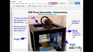
So
the
axes
are
y1
and
y2.
That's
the
y
y
axes,
the
x
axis
of
the
main
carriage
where
the
extruder
is
and
a
z
is
self-explanatory.
The
motor
is
on
the
bottom
of
the
z,
the
and
I'm
going
to
go.
Please
switch
over
to
slide
6,
because
this
will
be
important
for
most
people.
This
is
actually
a
picture.
A
I
just
took
right
now
as
it's
printing,
but
if
you
look
at
the
left
most
picture
on
slide
number
6
here,
that's
looking
under
the
bed,
so
you
see
the
z,
z,
motor
z,
axis
the
z
motors
on
the
bottom
and
it's
facing
towards
you
in
a
second
picture
that
here
you've
got
the
x-axis
the
main
carriage
the
extruder
is
towards
the
z-axis
right.
So
it's
it's
facing
the
z-axis,
it's
away
from
you
when
you're
looking
at
it.
So
this
is
this
is
orientation.
A
We
are
looking
at
it
from
the
front
and
this
is
the
official
orientation
you
look
at
it
from
the
front
and
then
the
wide
the
left
Y
motor
is
facing
towards
the
z
axis
it's
facing
towards
the
inside.
Obviously,
because
if
it
were
facing
the
other
way,
it
would
be
hitting
the
frame
and
it's
the
printed
pieces
that
attach
to
the
frame
and
on
the
right-hand
side
for
the
y
axis,
which
is
cut
off
here
a
little
bit.
But
you
see
that
picture
there.
A
The
Y
motor
y2,
where
y
2
is
the
right-hand
side
Y
axis.
Once
again,
the
motor
is
pointing
towards
the
z
axis.
So
they're
all
the
Y
motors
are
pointing
towards
the
inside
the
inner
part
of
the
machine
and
then
a
third
picture
here
you
see,
oh
yeah,
it's
more
detail
here
that
the
y
Y
motors
are
facing
towards
the
inside
towards
the
z
axis.
So
that's
that's
the
main
thing
about
orientation,
because
we
have
to
keep
very
good
track
of
orientation,
because
the
assembly
is
we're
going
to
build
to
build
all
the
axes.
A
But
then,
once
you
have
the
axes
built
how
you
assemble,
it
means
the
difference
between
assembling
at
one
time
and
three
times
like
we
did
last
time.
Like
last
time.
You
pretty
much
ended
up
assembling
things
like
three
times
over,
because
people
would
have
the
belt
the
wrong
way
or
the
motor
the
wrong
way.
Even
though
the
machine
was
right
there,
it's
actually
like,
when
you're
doing
a
whole,
build
it's
actually
quite
quite
challenging,
and
only
one
single
person
out
of
twelve
got
it
right
on
the
first
time.
A
A
Now
we
build
the
axes,
you
quality-control
the
axes
and
then,
when
you
assemble
the
axes
into
the
frame,
which
is
perhaps
the
most
critical
aspect
of
how
the
whole
thing
goes
together,
how
you
mount
the
axes
within
the
frame,
we
can
have
that
being
done
all
at
the
same
time
like
everyone
together,
so
you
can
basically
a
lot.
You
know,
look
at,
have
all
the
machines
down
an
aisle
and
you
can
see
like
right
there.
A
Okay
are
the
motor
spacing
the
right
way,
so
we
can
quality
control
that
right
there
as
we're
doing
it
not
person
by
person
you'll
be
a
whole
group,
because
we
found
that
when
people
are
staggered
and
people
are
different
steps,
it's
literally
impossible
to
quality
control
that,
because
there's
too
many
first,
you
have
to
see
okay.
Where
is
this?
What
step
is
this
person
on
and
what
did
I
need
to
look
for
in
practice,
that's
impossible.
A
If
you've
got
a
lot
of
people,
especially
as
we
scale
to
larger,
builds
like
100
3d
printers
in
a
single
day
like
in
Saudi
Arabia
in
November,
that
we're
planning
for
that's
actually
going
to
be
critical,
that
everyone's
at
the
same
step,
otherwise,
quality
control
is
impossible.
Unless
you
have
like
20
inspectors,
you
know
one
for
every
five
people
or
so
then
you
can
guarantee
it,
but
otherwise
you're
going
to
make
mistakes.
So
the
idea
of
working
all
at
the
same
time
really
matters,
and
especially,
if
we
have
these
languages,
not
the
constructions.
A
People
can
reference
the
build
instructionals
and
then
everyone
is
just
doing
the
same
thing.
So
everyone
is
aligned
and
we'll
really
try
to
stick
to
that.
I
know
we
try
to
have
everybody
go
at
the
same
same
step,
all
the
time
that
just
didn't
happen
in
practice.
So
this
time
around
we're
going
to
structure
the
event
that
we
make
sure
that
does
happen.
Okay.
So
let's
take
a
look
at
the
actual
assembly,
various
assemblies,
the
each
page.
A
So
after
starting
on
page
three,
we've
got
the
different
1
through
8,
so
referencing
between
page
1
and
and
3
the
final
assembly.
So
the
final
assembly
order
I
started
that
as
the
first
first
slide.
It's
really
slide
number
3
step
number
3,
but
it
is
that's
like
one
of
the
most
important
instructions
we
could
have,
because
that
shows
the
whole
workflow
they'll
move
that
into
the
third
position.
So
the
first
one
is,
of
course
the
axis
you
can
read
through
that,
so
one
is
access
and
right
after
that
is
the
belt.
A
Tensioning
I
actually
put
that
as
a
separate
step,
because
that's
it's
a
little
complicated,
so
I
think
that
just
deserves
a
separate
instructional
there.
So
in
fact,
I'm
going
to
just
add
that
axis
and
then
belt
tension
and
then
so
you've
got
belt
tension
0.3.
So
therefore
the
final
assembly
order
would
be
4
and
then
access
and
bed
fitting
to
frame
would
be
step.
Number
three,
so
you're
fitting
all
the
pieces
that
you
made
into
the
frame.
A
That's
like
one
one
good
step
so
here
we're
organizing
it
around
how
the
actual
build
happens,
whereas
before
with
a
exploded,
part
animation
videos.
We
had
individual
modules
here,
we're
talking
about
much
more
about
the
holistic
picture
of
how
it
actually
does
go
together.
So
so
that's
3
5
would
be
extruder
proof,
plus
wiring,
so
yeah
there's
a
whole
extruder
assembly
with
the
sensor,
including
the
mounting
piece,
how
you
mount
the
extruder
to
the
frame
which
is
magnetically
attached.
So
there's
all
these
details
a
little
details
there.
A
So
that's
we
have
that
up
to
here.
As
far
as
the
cable
chain,
that's
more
complicated,
we'll
see
if
we
have
enough
people
for
that
heat
bed
plus
support
that
comes
out
of
the
the
exploded
part
animation,
videos
that
we
can
basically
copy
all
the
steps
are
in
there.
So
basically
that's
good
to
go
I'm
going
to
put
the
cable
chain
in
red
since,
since
that
plus
the
controller
wiring
are
harder
harder
ones,
the
power
supply
up
to
the
green
connector,
and
that's
also
not
really
shown-
and
a
controller
not
really
shown
here.
A
A
A
But
the
final,
the
axis
fitting
to
frame
actually
should
be
the
number
one
thing
that
we
do
simply
because
that's
where
things
start
getting
confusing
and
people
start
making
mistakes,
essentially
the
axis
fitting
to
frame.
So
let's
do
that
is
number
one.
Let's
do
the
final
assembly
order
a
step
number
number
two
in
terms
of
prioritizing
an
extruder
as
three,
because
once
we
have
those
like
everything
else
is
pretty
much
straightforward.
So
let's
divvy
it
out.
A
A
A
But
it's
the
most
important,
so
we
should
do
it
and
in
this
example,
we
have
to
make
the
ISO
metrics
of
the
entire
axis
and
for
the
final
assembly
order,
we
have
to
have
the
ISO
metrics
of
all
the
different
pieces.
So
there's
a
lot
of
work
there.
Actually
so
maybe
extracting
the
the
workflow-
and
so
we
don't
get
overwhelmed
here
and
see
visible
progress
is
what
we
should
do
is
start
a
page
with
the
actual
extracted
images.
Well,
I
mean
it's
a
bunch
of
them,
so
but
I
think
we
should.
A
We
should
break
this
down
a
little
more.
So,
for
example,
when
you
have
the
axis
fitting
to
frame
I
mean
for
that,
you
have
to
extract
the
X
Y
Y
Z
and
the
frame,
so
you
got
to
get
all
those
ISO
metrics
and
for
the
ISO
metrics
I'm,
not
sure
if
it
matters
whether
you're
in
perspective
view
or
orthographic
view,
but
please
do
perspective
if
possible,
because
that
looks
better
I'm
going
to
make
that,
as
as
a
note
here
use
perspective
view
all
the
time.
A
A
A
Okay,
as
there's
a
lot
of
work
there,
so
let's
just
get
right
into
it,
divide
one
by
one
and
see
how
far
we
get
in
one
two
three
today,
sorry
one
two
four:
do
it
for
three
hours
and
see
how
far
we
get
to
the
final
final
Assembly's
final
yeah.
So,
let's,
let's
divvy
it
up.
Let's
do
it
so
who
wants
to
do
I?
Think
Roberto,
since
he
wrote
the
book
on.
A
This
should
probably
do
the
maybe
the
final
assembly
order,
maybe,
but
for
that
we
need
to
extract
part
by
part,
so
XY
Y,
Z
frame,
heated
bed
plus
all
those
elements
so
one
by
one
like
final
assembly
order
and
the
way
you
can
start
that
is
go
into
the
video
playlist.
There's
a
video
there
already
on
the
final
assembly
order.
A
So
just
pretty
much
replicate
that,
because,
because
that
video
by
Jose
there
that's
a
good
video
on
the
final
assembly
order
and
it's
missing
some
of
the
things-
that's
missing-
I-
think
the
cable
chain
and
controller
and
power
supply.
Now,
if
we
don't
have
the
cable
chain,
controller
and
power
supply
the
cable
chain,
I
know
we
have
it,
we
might
have
to
reconfigure
it
yeah
yeah.
We
do
have
the
cable
chain,
we
don't
really
have
the
controller,
but
what
we
could
do
there
simply
is
do
a
very
simple
place
holder.
A
It's
like
a
you
know,
a
2
by
3
inch
rectangle
to
become
a
the
power
supply.
We
actually
did
for
the
linemen
filament
maker.
We
can
borrow
it
from
there,
but
then
you
can
represent
it
as
simply
a
box.
So
let's
do
it
final
assembly
order.
Okay,
Roberto
can
I
get
you
started
on
that.
Then
you
think
you
can
do
that.
One!
That's
that's
kind
of
like
the
biggest
one.
A
C
B
A
Okay,
we
can.
We
can
try
that
so,
but
maybe
okay
yeah,
let's
let's
try
it
if
it's,
if
it's
terrible,
I
so
yeah
go
to
this
link
here,
open
source,
ecology
meet
Doug,
Betsy
and
I
have
both
of
them
open
right
now.
So,
let's
see,
if
people
migrate
over
there,
you
can
actually
open
both
of
them.
If
you
have
enough
bandwidth
like
I'm
over
at
jitsi,
already,
okay,
so
I
see
people
coming
in
Abe,
Josh
Roberto.
A
C
A
A
A
Okay,
muted,
that
person-
okay,
so
let's,
let's
start
it
so
that
one
of
the
biggest
parts
in
this
exercise
is
where
how
do
we
keep
track
of
everything?
So
what
I
would
suggest
right
here
is,
after
each
individual
slide,
just
start
putting
your
your
images
in
there.
So
your
SVG
file,
that's
been
cleaned
up
exported
according
to
the
procedure,
but
do
link
to
your
working
cat
file
in
this
document
and
to
begin
with
I
think
we
should
get
clear
on
what
the
main
working
file
is.
A
So
we
probably
want
to
go
to
the
3d
CAD
page
on
the
wiki
and
use
the
16
inch
final
assembly
and
that
I
believe,
let's
see
what
is
the
no
that's,
not
the
right
page.
So
if
you
go
to
the
d3d
page
on
the
final
final
assembly
should
be
lengths.
So
if
you
click
on
cat
on
the
D
3d
CAD
final
assembly
link
is
the
one
that
is
so.
It
looks
like
uh-huh.
A
A
A
A
A
B
A
And
as
we
go
here,
so
let's
divvy
it
up
to
divvy
up
the
work
to
different
people
and
maybe
seems
gonna
take
a
little
bit
of
time.
Let's
work
on
it
collaboratively
and
since
we
only
have
till
Saturday
morning
to
do
this
well,
I
would
suggest
suggest.
Oh,
is
that
we
maybe
team
up
a
little
bit
as
much
as
we
can.